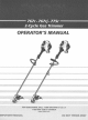
THANK YOU L Thank you for buying this quality product. This modem outdoor power tool will provide many hours of useful service. You will find it to be a great labor-saving device. This operator's manual provides you with easy-tounderstand operating instructions. Read the whole manual and follow all the instructions to keep your new outdoor power tool in top operating condition.
THE ENGINE EXHAUST FROM THIS PRODUCT CONTAINS CHEMICALS KNOWN TO THE STATE OF CALIFORNIA TO CAUSE CANCER, BIRTH DEFECTS OR OTHER REPRODUCTIVE HARM, NOTE: For users on U.S. Forest Land and in the states of California, Maine, Oregon and Washington. All U.S.
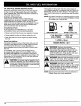
• IMPORTANT SAFETY INFORMATION READ ALL INSTRUCTIONS • • Read the instructions carefully. Be familiar with the controls and proper use of the unit. • Add fuel in a clean, well-ventilated area outdoors where there are no sparks or flames. Slowly remove the fuel cap only after stopping engine. Do not smoke while fueling or mixing fuel. Wipe up any spilled fuel from the unit immediately. • Do not operate this unit when tired, ill, or under the influence of alcohol, drugs, or medication.
• To reduce fire hazard, replace faulty muffler and spark arrestor, keep the engine and muffler free from grass, leaves, excessive grease or carbon build up. , Do not touch the engine, gear housing or muffler. These parts get extremely hot from operation. When turned off they remain hot for a short time, OTHER Do not operate the engine faster than the speed needed to cut, trim or edge. Do not run the engine at high speed when not cutting.
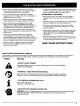
SYMBOL MEANING • KEEP BYSTANDERS A AWAY WARNING: Keep all bystander_, from the operating area. 5-7x • PRIMER especially children and pets, at least 50 feet (15 m) BULB Push primer bulb, fully and slowly, 5 to 7 times, • UNLEADED FUEL Always use clean, fresh unleaded fuel. • OIL Refer to operator's manual for the proper type of oil.
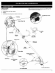
APPLICATIONS As a trimmer; Other optional accessories may be used with the 775r. See list of add-ona on page 12. • Cutting grass and light weeds. • Edging • Decorative trimming around trees, fences, etc. On/Off Stop Control Fuel Cap Starter Rope Grip Shaft Grip D-Handle 767r / \ Throttle Control J-Handle 767rj, 775r Choke Lever Clink-Link 775r Only / Shaft Housing Primer Bulb Cutting Attachment Shield Muffler Spark Plug \ Air Filter/Muffler Cover I Line Cutting Blade Cutting Attachment
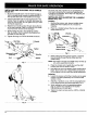
INSTALLING Model 767r AND ADJUSTING THE D-HANDLE 1. Push the D-handle down onto the shaft housing so that the handle slants towards the shaft grip (Fig. 1). The squared bolt hole in the handle is to the right. 2. Insert the shoulder bolt into the squared hole in the handle. Place the washer on the bolt, and screw the wing nut onto the bolt. Do not tighten until you make the handle adjustment, 3. 4. Rotate the D-handle to place the grip above the top of the shaft housing.
-... Cutting Attachment Shield Shield Mount Cutting Attachment ................... 2. Fig. 6 ........ Place a he× lock nut into one of the three recessed holes on the top of the cutting attachment shield (Fig 7. Cutting Attachment Shield ........... Fig. 5 INSTALLING SHIELD THE CUTTING ...... .................. ATTACHMENT Use the following instructions if the cutting attachment shield on your unit is not installed. [ ,_ 1.
OIL AND FUELMIXINGINSTRUCTIONS Old and/or improperly mixed fuel are the main reasons for the unit not running properly, Be sure to use fresh, clean unleaded fuel. Follow the instructions carefully for the proper fuel/oil mixture. Definition of Blended Fuels Todayls fuels are often a blend of gasoline and oxygenates such as ethanol, methanol or MTBE (ether). Alcohol-blended fuel absorbs water. As little as 1% water in the fuel can make fuel and oil separate. It forms acids when stored.
STARTING I,_ INSTRUCTIONS ventilated area outdoors. Carbon monoxide exhaust fumes can be lethal in a confined ARNING" Operate this unit only in a well area. WARNING; Avoid accidental starting. Be in the starting position when pulling the starter rope (Fig. 11). The operator and unit must be in a stable position while starting to avoid serious personal injury.
OPERATING 775r Only THE CLICK-LINK ® SYSTEM 2. The Click-Link ® system enables the use of these optional add-ons. Blower/Vacuum .......................... BV720r Cultivator .............................. NOTE; Aligning the release button with the gu{de recess will help installation (Fig. 12). GC72Or Edger .................................. LE720r Hedge Trimmer .......................... Snow Thrower ........................... HS720r ST720r Straight Shaft Trimmer ....................
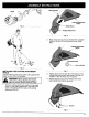
HOLDING THE TRIMMER WARNING: Always wear eye, hearing, foot and body protection to reduce the risk of injury when operating this unit, Before operating the unit, stand in the operating position (Fig. 15). Check for the following: • The operator is wearing eye protection and proper clothing, • The right arm is slightly bent, and the hand is holding the shaft grip. • The left arm is straight, and the hand is holding the D-Handle or J-handle. • The unit is at waist level.
DECORATIVETRIMMING Decorative trimming is accomplished by removing all vegetation around trees, posts, fences, etc, Rotate the whole unit so that the cutting attachment is at a 30 ° angle to the ground (Fig, 17). ..... NOTE: Some maintenance procedures may require special tools or skills. If you are unsure about these procedures take your unit to an authorized service dealer. MAINTENANCE l,_ SCHEDULE Fig. 17 ............ do maintenance or repairs with unit running.
LINE INSTALLATION FOR THE SPEEDSPOOL ® Always use genuine Ryobi 0.080 inch (2.03 mm) replacement line. Line other than specified may make the engine overheat or fail. wire, chain, or rope, etc. These can break off WARNING: Never use metal-reinforced line, and become a dangerous projectile. _ Trimming Line -_ I Eyelet There are two methods to replace the SpeedSpool ® trimming line. • Wind the inner reel with new line Line Loading Hole • Install a prewound inner reel ....
7. Repeat procedures 4-6 with the second piece of line. 8. Hold the outer spool. Wind the inner reel counterclockwise until approximately four (4) inches (102 mm) of line remain (Fig. 22). Bump Knob Foam NOTE: Do not wind the inner reel before installing the second piece of line. I inner Ree! __ Fig. 24 2. Pull the old inner reel with existing line from the outer spool, 3, Insert the ends of the prewound inner reel line into the outer spool eyelets (Fig. 25).
CLEANING THESPEEDSPOOL ® . Cleaning the SpeedSpool ® may be necessary, • To remove jammed or excess line, • If the SpeedSpool ® becomes difficult to wind or does not operate correctly when bumping the head on the ground, 1. Hold the outer spool, and unscrew the bump knob counterclockwise (Fig. 26). Clean the shaft and the inner surface of the outer spool. To clean the shaft underneath the plunger, press down on the plunger (Fig. 28). Remove any dirt or debris from the shaft. Shaft Plun Fig. 28 ...
AIR FILTER MAINTENANCE Removing the Air Filter/Muffler I j_ AA, Cover WARNING: To avoid serious personar injury, always turn your trimmer off and allow it to cool before you clean or do any maintenance on it. 1. Place the choke lever in the PARTIAL choke position (B). Air Filter NOTE: The choke lever must be in the PARTIAL choke position (B) (Fig, 29) to remove the air filter/muffler cover. 2. Remove the four (4) screws securing the air filter/muffler cover (Fig. 29).
5_ If after checking the fuel mixture and cleaning the air filter the engine still will not idle, adjust the idle speed screw as foltows. Squeeze the filter to spread and remove excess oil (Fig. 33). . 2. Start the engine and let it run at a high idle for a minute to warm up. See Starting/Stopping Instructions, Pg. 11. Release the throttle trigger and let the engine idle. If the engine stops, insert a small phillips or flat blade screwdriver into the hole in the air filter/muffler cover (Fig. 34).
REPLACING CLEANING THE SPARK PLUG Use a Champion RDJTY spark plug (or equivalent). The correct air gap is 0.020 inch (0.5 mm.). Remove the plug after every 50 hours of operation and check its condition. 1. Stop the engine and allow it to cool. Grasp the plug wire firmly and pull it from the spark plug. 2. . Clean around the spark plug. Remove the spark plug from the cylinder head by turning a 5/8 in. socket counterclockwise. Replace cracked, fouled or dirty spark plug. Set the air gap at 0.020 in, (0.
CAUSE ACTION On/Off Stop Control is in OFF position T_rn On/Off Stop Control to ON Empty fuel tank Fill fuel tank with properly mixed fuel Primer bulb wasn't pressed enough Press primer bulb fully and slowly 5-7 times Engine flooded Use starting procedure with choke lever in the RUN position, Pg.
Engine Type ................................................................. Stroke ....................................................................... Displacement ................................................................... Clutch Type ......................................................................... Idle Speed RPM ................................................................. Operating RPM ................................................................. Ignition Type .............
MANUFACTURER'S LIMITED WARRANTY FOR: RYOBIo The limited warranty set forth below is given by MTD SOUTHWEST INC ("MTD") with respect with new merchandise purchased and used in the United States, its possessionsand territories. MTD warrants this product against defects in material and workmanshipfor a periodof two (2) years commencingon the date of original purchase and will, at its option, repair or replace, free of charge, any part found to be defective in material or workmanship.