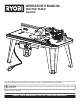
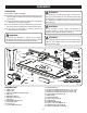
OPERATOR’S MANUAL ROUTER TABLE A25RT02 3 2 1 0 1 Inch 3 2 inch 1 0 1 Inch Your router table has been engineered and manufactured to our high standard for dependability, ease of operation, and operator safety. When properly cared for, it will give you years of rugged, trouble-free performance. WARNING: To reduce the risk of injury, the user must read and understand the operator’s manual before using this product. Thank you for your purchase.
TABLE OF CONTENTS Introduction ..................................................................................................................................................................... 2 Warranty .......................................................................................................................................................................... 2 General Safety Rules ........................................................................................................
GENERAL SAFETY RULES ALWAYS WEAR SAFETY GLASSES WITH SIDE SHIELDS. Everyday eyeglasses have only impactresistant lenses, they are NOT safety glasses. WARNING: Read and understand all instructions. Failure to follow all instructions listed below, may result in electric shock, fire and/or serious personal injury. SECURE WORK. Use clamps or a vise to hold work when practical, it is safer than using your hand and frees both hands to operate the tool. READ ALL INSTRUCTIONS DO NOT OVERREACH.
GENERAL SAFETY RULES INSPECT TOOL CORDS PERIODICALLY. If damaged, have repaired by a qualified service technician at an authorized service facility. The conductor with insulation having an outer surface that is green with or without yellow stripes is the equipment-grounding conductor. If repair or replacement of the electric cord or plug is necessary, do not connect the equipment-grounding conductor to a live terminal. Repair or replace a damaged or worn cord immediately.
SYMBOLS Some of the following symbols may be used on this product. Please study them and learn their meaning. Proper interpretation of these symbols will allow you to operate the product better and safer.
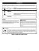
SYMBOLS The following signal words and meanings are intended to explain the levels of risk associated with this product. SYMBOL SIGNAL MEANING DANGER: Indicates an imminently hazardous situation, which, if not avoided, will result in death or serious injury. WARNING: Indicates a potentially hazardous situation, which, if not avoided, could result in death or serious injury. CAUTION: Indicates a potentially hazardous situation, which, if not avoided, may result in minor or moderate injury.
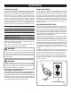
ELECTRICAL EXTENSION CORDS SPEED AND WIRING Use only 3-wire extension cords that have 3-prong grounding plugs and 3-pole receptacles that accept the product’s plug. When using a power product at a considerable distance from the power source, use an extension cord heavy enough to carry the current that the product will draw. An undersized extension cord will cause a drop in line voltage, resulting in a loss of power and causing the motor to overheat.
FEATURES PRODUCT SPECIFICATIONS Table Dimensions ................................ 16 in. x 32 in. x 1 in. Maximum Cutter Diameter .................................1-15/16 in. Fence Length ............................................................. 28 in. VACUUM PORT Miter Slot ........................................ 1/4 in. x 3/4 in. x 32 in. Rating .............................. 120 V, 60 Hz, AC only, 15 Amps Net Weight .................................................................28 lbs.
FEATURES RESET BUTTON WARNING: See Figure 2. Always remove the switch key when the tool is not in use and keep it in a safe place. In the event of a power failure, turn the switch OFF ( O ) and remove the key. This action will prevent the tool from accidentally starting when power returns. The router table switch is equipped with a reset button that protects the electronic components of the router table switch box from overload.
ASSEMBLY UNPACKING WARNING: This product requires assembly. Do not attempt to modify this product or create accessories not recommended for use with this product. Any such alteration or modification is misuse and could result in a hazardous condition leading to possible serious personal injury. Carefully remove the product and any accessories from the box. Make sure that all items listed in the packing list are included.
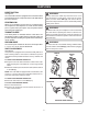
ASSEMBLY ASSEMBLING THE ROUTER TABLE Assembling the router table involves attaching the switch box, the under table guards, the legs, the router/insert plate assembly, the fence assembly, featherboard, throat plate, starting pin, and installing the miter gauge to the router table. SWITCH KEY SWITCH BOX SWITCH BOX NUT ATTACHING THE SWITCH BOX See Figure 5. The switch box will come in a bag with the switch box screws and nuts. Use these screws and nuts in the bag to attach the switch box.
ASSEMBLY PRE-DRILLING HOLES FOR THROUGH TABLE DEPTH ADJUSTMENT INSERT PLATE REAR SIDE PRE-DRILLED PILOT HOLES See Figure 8. Since each router will have different placements for through table depth adjustments, pilot holes have been pre-drilled in the throat plate to assist in through table adjustments. Only the models listed below in the key are available for use with the through table depth adjustment feature. Remove the throat plate.
ASSEMBLY BRAND MODEL BASE TYPE FASTENER SIZE INSERT PLATE HOLES USED NUMBER OF HOLES Bosch 1617 Fixed 10-24 x 5/8 in. A1, A3, A5 3 Bosch 1617 EVS Fixed 10-24 x 5/8 in. A1, A3, A5 3 Bosch 1617 EVSPK Fixed 10-24 x 5/8 in. A1, A3, A5 3 Craftsman 17504 Fixed 10-32 x 5/8 in. A2, A4, A6 3 Craftsman 17505 Fixed 10-32 x 5/8 in. A2, A4, A6 3 Craftsman 17506 Fixed 10-32 x 5/8 in. A2, A4, A6 3 Craftsman 17508 Fixed 10-32 x 5/8 in.
ASSEMBLY MAKING INSERT PLATE LEVEL See Figure 12. Unplug the router table and/or the router. Check to see if the insert plate mounted assembly is level with a straight edge or level. Loosen insert plate screws. Using the supplied hex key, tighten or loosen the adjusting screws depending on how the insert plate needs to be adjusted in order to make the insert plate level. Tighten insert plate screws with a screwdriver.
ASSEMBLY Unplug the router table and/or the router. Select the throat plate you wish to use. SLOT FEATHERBOARD BOLT Press throat plate into insert plate slot until it snaps into place. 3 2 To remove, push throat plate out from the bottom of the insert plate. 1 0 1 Inch ATTACHING THE FEATHERBOARD See Figure 15. Unplug the router table and/or the router. Insert the featherboard bolts through the slots in the fence assembly. Slide the featherboard over the featherboard bolts.
ASSEMBLY ATTACHING THE VACUUM HOSE VACUUM PORT See Figure 18. The vacuum port molded into the fence will accept either a 1-1/4 in. or 2-1/2 in. vacuum attachment. CLAMPING THE ROUTER TABLE TO A WORK BENCH F D EE IR D E C T IO See Figures 19. Unplug the router table and/or the router. Place the router table right side up on a sturdy work surface; e.g., leg stand, workbench, counter top. Using a clamp, insert the top front of clamp through the opening in the router table leg.
OPERATION WARNING: WARNING: Do not allow familiarity with products to make you careless. Remember that a careless fraction of a second is sufficient to inflict serious injury. The router or router table should never be connected to a power supply when you are assembling parts, making adjustments, installing or removing cutters, cleaning, or when not in use. Disconnecting the router and router table will prevent accidental starting that could cause serious personal injury.
OPERATION INSERTING/REMOVING CUTTERS MITER GAUGE KNOB Unplug the router table and/or the router. Remove the router/insert plate assembly. (See Installing Router/Insert Plate Assembly in the Assembly section.) 3 2 1 0 WARNING: 1 Inch If you are changing a cutter immediately after use, be careful not to touch the cutter or collet with your hands or fingers. They will get burned because of the heat buildup from cutting. Always use a wrench.
MAINTENANCE WARNING: WARNING: When servicing, use only identical replacement parts. Use of any other parts may create a hazard or cause product damage. Do not at any time let brake fluids, gasoline, petroleumbased products, penetrating oils, etc., come in contact with plastic parts. Chemicals can damage, weaken or destroy plastic which may result in serious personal injury.
OPERATOR’S MANUAL ROUTER TABLE A25RT02 WARNING: Some dust created by power sanding, sawing, grinding, drilling, and other construction activities contains chemicals known to cause cancer, birth defects or other reproductive harm. Some examples of these chemicals are: • lead from lead-based paints, • crystalline silica from bricks and cement and other masonry products, and • arsenic and chromium from chemically-treated lumber.