OPERATOR’S MANUAL Expand-it™ Pruner Attachment UT15520C Your Expand-it™ Pruner Attachment has been engineered and manufactured to a high standard for dependability, ease of operation, and operator safety. When properly cared for, it will give you years of rugged, trouble-free performance. WARNING: To reduce the risk of injury, the user must read and understand the operator’s manual before using this product. Thank you for buying an Expand-it™ product.
TABLE OF CONTENTS Introduction ................................................................................................................................................................... 2 General Safety Rules .................................................................................................................................................... 3 Specific Safety Rules ..............................................................................................................
GENERAL SAFETY RULES Do not overreach. Keep proper footing and balance at all times. Proper footing and balance enables better control of the tool in unexpected situations. WARNING: Read and understand all instructions. Failure to follow all instructions listed below, may result in electric shock, fire, and/or serious personal injury. Keep all parts of your body away from any moving part. Do not touch areas around the muffler or cylinder of the power head. These parts get hot from operation.
SPECIFIC SAFETY RULES Do not force tool. Use the correct tool for your application. The correct tool will do the job better and safer at the rate for which it is designed. Kickback is a dangerous reaction that can lead to serious injury. Kickback may occur when the moving chain contacts an object at the upper portion of the tip of the guide bar or when the wood closes in and pinches the chain in the cut.
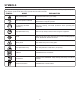
SYMBOLS Some of the following symbols may be used on this tool. Please study them and learn their meaning. Proper interpretation of these symbols will allow you to operate the tool better and safer. SYMBOL NAME EXPLANATION Safety Alert Symbol Precautions that involve your safety. Read The Operator’s Manual To reduce the risk of injury, user must read and understand operator’s manual before using this product.
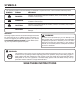
SYMBOLS The following signal words and meanings are intended to explain the levels of risk associated with this product. SYMBOL SIGNAL MEANING DANGER: Indicates an imminently hazardous situation, which, if not avoided, will result in death or serious injury. WARNING: Indicates a potentially hazardous situation, which, if not avoided, could result in death or serious injury. CAUTION: Indicates a potentially hazardous situation, which, if not avoided, may result in minor or moderate injury.
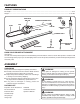
FEATURES PRODUCT SPECIFICATIONS Bar length ........................................................................................................................................................................10 in. Weight ...................................................................................................................................................................... 5-1/2 lbs.
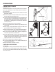
ASSEMBLY CONNECTING POWER HEAD TO EXTENSION SHAFT AND PRUNER ATTACHMENT See Figure 2. The pruner attachment connects to the power head or, for extra reach, to an extension shaft by means of a coupler device. GUIDE RECESS COUPLER POWER HEAD SHAFT BUTTON WARNING: Never attach or adjust any attachment while power head is running. Failure to stop the engine may cause serious personal injury.
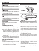
OPERATION WARNING: LOAD Do not allow familiarity with tools to make you careless. Remember that a careless fraction of a second is sufficient to inflict serious injury. SECOND CUT FIRST CUT 1/4 DIAMETER WARNING: Always wear safety goggles or safety glasses with side shields when operating power tools. Failure to do so could result in objects being thrown into your eyes resulting in possible serious injury. FINAL CUT Fig.
OPERATION LIMBING AND PRUNING See Figures 7 - 8. This unit is designed for trimming small branches and limbs up to 6 in. in diameter. For best results, observe the following precautions: Plan the cut carefully. Be aware of the direction in which the branch will fall. � Branches may fall in unexpected directions. Do not stand directly under the branch being cut. 60° MAXIMUM � The most typical cutting application is to position the unit at an angle of 60° or less, depending on the specific situation.
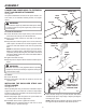
MAINTENANCE WARNING: CHAIN When servicing, use only identical replacement parts. Use of any other parts may create a hazard or cause product damage. BAR DRIVECASE COVER BAR NUT WARNING: Fig. 10 Always wear safety goggles or safety glasses with side shields during power tool operation or when blowing dust. If operation is dusty, also wear a dust mask.
MAINTENANCE Place the bar onto the bar stud so that the chain tensioning pin fits into the chain tensioning pin hole. Fit the chain over the sprocket and into the bar groove. The cutters on the top of the bar should face toward the bar tip, in the direction of the chain rotation. Replace the drive case cover and reinstall the bar nut. Tighten the bar nut finger tight only; the bar must be free to move for tension adjustment.
MAINTENANCE CHAIN TENSION See Figures 17 - 18. Stop the engine before setting the chain tension. Make sure the guide bar nut is loose to finger tight, turn the chain tensioning screw clockwise to tension the chain. Refer to Replacing the Bar and Chain for additional information. FLATS A cold chain is correctly tensioned when there is no slack on the underside of the guide bar and the chain is snug, but can be turned by hand without binding. Fig.
MAINTENANCE CHAIN MAINTENANCE DEPTH GAUGE SETTING See Figure 20. WARNING: The chain is very sharp; always wear protective gloves when performing maintenance to the chain. Fig. 20 Use only the replacement low kickback chain specified for this unit. For smooth and fast cutting, the chain needs to be maintained properly. The chain requires sharpening when the wood chips are small and powdery, the chain must be forced through the wood during cutting, or the chain cuts to one side.
MAINTENANCE CAUTION: Dull or improperly sharpened chain can cause excessive engine speed during cutting, which may result in severe engine damage. HANGER CAP ATTACHING THE STORAGE HANGER HOLE See Figure 25. There are two ways to hang the attachment for storage. To use the hanger cap, push in the button and place the hanger cap over end of the lower end attachment shaft. Slightly rotate the cap from side to side until the button locks into place.
EXPLODED VIEW AND PARTS LIST 1 2 3 4 5 6 8 7 32 12 9 10 11 14 13 9 17 34 15 16 18 33 35 19 31 20 30 21 36 22 29 28 27 26 23 37 24 25 38 16
EXPLODED VIEW AND PARTS LIST Key No. Part No. Description Qty. 1 300949002 Oil Cap Assembly . . . . . . . . . . . . . . . . . . . . . . . . . . . . . . . . . . . . . . . . . . . . . . . .1 2 660934001 * Screw (M5 x 18 mm) . . . . . . . . . . . . . . . . . . . . . . . . . . . . . . . . . . . . . . . . . . . . . .4 3 308512001 Oil Tank Cover Assembly . . . . . . . . . . . . . . . . . . . . . . . . . . . . . . . . . . . . . . . . . .1 4 901374001 Oil Cover Gasket. . . . . . . . . . . . . . . . .
NOTES 18
WARRANTY LIMITED WARRANTY STATEMENT In addition, this warranty does not cover: A. Tune-ups – Spark Plugs, Carburetor, Carburetor Adjustments, Ignition, Filters B. Wear items – Bump Knobs, Outer Spools, Cutting Lines, Inner Reels, Starter Pulleys, Starter Ropes, Drive Belts, Tines, Felt Washers, Hitch Pins, Mulching Blades, Blower Fans, Blower and Vacuum Tubes, Vacuum Bags and Straps, Guide Bars, Saw Chains Techtronic Industries North America, Inc.
OPERATOR’S MANUAL Expand-it™ Pruner Attachment UT15520C SERVICE For parts or service, contact your nearest Expand-it™ authorized service center. Be sure to provide all relevant information when you call or visit. For the location of the authorized service center nearest you, please call 1-800-242-4672 or visit us online at www.homelite.com. REPAIR PARTS The model number of this tool is found on a plate or label attached to the housing. Please record the serial number in the space provided below.