
Technical data


Technical documentation
Technical documentation
STZS ed 06/03
5
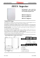
ZEUS SUPERIOR
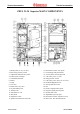
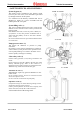
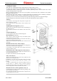
HYDRAULIC CIRCUIT
1 - Storage tank drain valve
2 - One way valve
3 - Coil
4 - Gas valve
5 - Magnesium anode
6 - Storage tank
7 - Pump
8 - Burner
9 - Combustion chamber
10- Primary heat exchanger
11- Flue hood
12- Fan
13- Flue safety pressure switch
14- Sealed room
15- Adjustment and limit NTC probe
16- Automatic air vent
17- Expansion vessel
18- Overheating safety thermostat
19- Pump pressure switch
20- Pump pressure meter
21- Domestic hot water. NTC probe
22- System drain valve.
23- Motorised 3-way valve
24- System filling valve
25- Adjustable system by-pass
26- 3 bar safety valve
27- D.h.w. expansion vessel
28- 8 bar d.h.w. safety valve
29- Gaudium Magnum device
30- Cold water inlet filter
31- Max flow limit thermostat
G – Gas supply
U – Domestic hot water outlet
E – Domestic cold water inlet
R – System return
M – System delivery
The hot water for the heating system and for the domestic circuit is produced by a primary circuit
and a secondary (domestic) circuit that are activated according to demand.
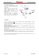
PRIMARY CIRCUIT (BOILER CIRCUIT)
The primary circuit with the relative control and safety devices is activated with each heating or
domestic circuit demand for water.
- OPERATION
The copper blades of the water-gas exchanger (10) absorb the heat contained in the flue gas
produced by combustion.
Those blades then transfer the heat to the water being circulated inside by the boiler pump (7).
The water is introduced directly into the plant or can be deviated inside the cylinder coil (3).
This depends on the position of the electric 3-way valve (23) which, depending on the demand,
allows water to flow through the plant delivery (M) and return (R) pipes or deviates it to the coil (3).