
Technical data


Technical documentation
Technical documentation
STZS ed. 06/03
21
ZEUS SUPERIOR
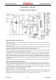
ELECTRICAL CIRCUIT
CENTRAL-HEATING PHASE
Operation with room thermostat
When the mainr switch (IG) is in WINTER position, it powers the modulation card and enables operation in
central heating mode.
When the room thermostat contact (TA) is closed, the low-voltage circuit starts the pump (MP) by closing the
contact of relay K2.
The circulation of water causes the pump pressure switch (SP) to close and, because this is connected in series
with the NC contact of the flue pressure switch (SV), the coil of relay K5 is energised.
Meanwhile, the adjustment circuit causes the deviation of the relay contact K3.
This way, the motor (M) of the 3-way valve (VD) is powered and continues to operate until the limit switch
"N" opens once the central heating position has been reached.
If the temperature read by the NTC heating sensor (NR) is below that set on the control panel with the heating
potentiometer, the low-voltage circuit excites the relay K5 and starts the fan (MV) commanding the relay K1.
The consequent deviation of the flue pressure switch (SV) powers the relay K4 the contact of which, on
closing, enables the control unit (IGN. UNIT) to start the ignition cycle, commanding first of all the ignition
electrodes (E1-E2) and then, with the consensus of the overheating thermostat (TS), both the main coils of the
gas valve (V/G).
Ignition of the burner is detected by the control unit (IGN. UNIT) by means of the ionisation electrode (E3).
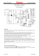
Operation with Remote Friend Control
The main switch (IG) in SUMMER position powers the modulation board and remote control (CAR).
If the conditions found by the remote control (CAR) require ignition in central heating phase
(SUM/WINT switch in WINTER position, central-heating temperature setting above that read by the
central-heating sensor NR, request by the time programmer, room temperature adjustment above that
read), the board powers pump MP through relay K2 contact.
Burner ignition then occurs as described above.
NOTE: In both cases, at each switch-off due to temperature having been reached, the modulation board
stops burner operation during central-heating phase for 180 seconds., which can be reduced to 30
seconds by intervening on the special jumper (J1) (see modulation card operation).