
Technical data


Technical documentation
Technical documentation
STZS ed 06/03
13
ZEUS SUPERIOR
GAS ADJUSTMENTS
Max and minimum gas pressure adjustments can be made respecting the values shown on the
page’s 31 and 32.
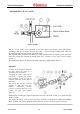
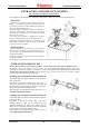
- SIT 845 VALVE
After having connected the leads of
a differential pressure gauge to the
gas valve outlet (4) and to the
positive pressure connector at the
top of the sealed chamber (see
figure), do the following :
Maximum pressure setting
- Do a d.h.w. request (open a tap)
and setting the temperature selector
at maximum.
Turn nut “3” clockwise to increase
the pressure to the burner and
counter-clockwise to reduce it.
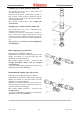
Minimum pressure setting
(to carry out after the maximum
pressure setting)
- After cutting off the power supply
to the modulation coil, turn screw
“2” clockwise to increase the
pressure to the burner and counter-
clockwise to reduce it.
1) Modulation coil 4) Gas valve outlet pressure connector
2) Min. power setting screw 5) Gas valve inlet pressure connector
3) Max. power setting screw 6) Protective cap
- CHANGING TYPE OF GAS
Adaptation to a type of gas different to that for which the boilers are intended, can be done by using the
special kits (natural gas or LPG).
The changeover consists in replacing the burner nozzles and in moving to the modulation board of the
“NATURAL GAS- LPG” (CM3) bridge.
The minimum and maximum pressures are then set on the gas valve in the way described above.
Adjustment of the minimum and maximum output during the heating phase and of burner ignition
pressure (see table below) can be done by means of the respective trimmers mounted on the modulation
board (see modulation board operation).
Soft ignition values in mbar (mm H
2
O)
Natural gas LPG
ZEUS 21/24 Superior 25 65
ZEUS 27 Superior 23 70