
Technical data


Technical documentation
Technical documentation
STZS ed 06/03
12
ZEUS SUPERIOR
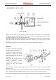
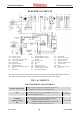
GAS CIRCUIT
The circuit consists of an atmospheric burner and a modulating type valve for gas combustion
and gas flow adjustment respectively.
- OPERATION
When the main coils (3) are energized, both inner valve shutters open, allowing the gas to flow
towards the burner.
The flow rate/outlet pressure is regulated by means of the gas valve stabilizer and the modulation
coil.
By means of the burner nozzles (7), the fuel is injected into the venturi pipes (ramps) inside which
the air-gas mix is obtained that is ignited by the spark from the ignition electrodes (5).
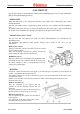
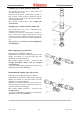
- MODULATING GAS VALVE
The gas valve (SIT 845) features two main coils and a third modulation coil controlled by the
adjustment board.
The maximum and minimum outlet pressure settings can be made on this valve (see gas
adjustments).
Main electric coils (3)
These two ON-OFF coils are fed (230 Vac) by the control
card to ignite the burner.
They are electrically connected in parallel and fed by
mains voltage through a special connector (2).
Modulation coil (1)
This low-voltage coil is controlled by the modulation card.
It controls the gas valve stabilizer and can be used to vary
the outlet pressure so that it is proportional to the d.c.
signal conveyed through it.
SIT 845
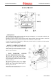
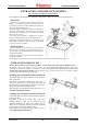
- BURNER
The burner consists of horizontal venturi pipes (6) in which the gas is injected by an equal number of
nozzles (7) mounted on the special header (8).
The number of nozzles is 13 in the 21,000 kcal/h version, 15 in the 24,000 kcal/h version and 16 in the
27,000 kcal/h version .
Ignition occurs by means of an electronic board (unit) which controls the ignition electrode (5) and
detection electrode (4).
Ignition electrodes (5)
They are controlled by the ignition unit that
generates an electric discharge between the two
electrodes.
They are mounted on the front of the burner between
the first and the second gas ramp (Venturi tube).
Detection electrode (4)
This is controlled by the ignition unit and detects
burner ignition.
It is positioned on the front of the burner on the
ramp alongside the ignition electrodes.