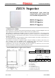
Technical documentation Technical documentation ZEUS Superior Wall-mounted, room sealed fan assisted boiler with storage tank and Gaudium Magnum device ZEUS 21 Superior ZEUS 24 Superior ZEUS 27 Superior - GENERAL FEATURES ZEUS Superior is a wall-hung room sealed fan-assisted boiler featuring a "Gaudium Magnum" device for fully exploiting the characteristics of this 54 l boiler in AISI 316L stainless steel.
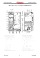
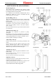
Technical documentation Technical documentation ZEUS 21-24 Superior MAIN COMPONENTS 1 - Intake points (A=air) (F=flue) 2 - Flue safety pressure switch 3 - Adjustment and limit NTC probe 4 - Primary heat exchanger 5 - Combustion chamber 6 - Burner 7 - Pump 8 - Gas valve 9 - Motorized 3-way valve 10 - System filling valve 11- Sealed room 12- Automatic air vent 13- Flue hood 14- Expansion vessel 15- Ignition and detection electrodes STZSC ed 06/03 16- Domestic hot water NTC probe 17- Overheating safety th
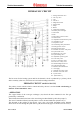
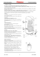
Technical documentation Technical documentation ZEUS 27 Superior MAIN COMPONENTS 16- Domestic hot water. NTC probe 17- Overheating safety thermostat 18- 316L stainless steel storage tank 19- 3 bar safety valve (system) 20- Pump pressure switch 21- 8 bar safety valve (d.h.w.
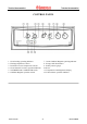
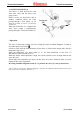
Technical documentation Technical documentation CONTROL PANEL 7 - Green Gaudium Magnum operating indicator 8 - Storage tank thermometer 9 - Boiler pressure gauge 10- Reset 11- Temperatures and diagnostics display 12- Yellow burner operation indicator 1 - Green heating operating indicator 2 - Heating temperature selector 3 - Domestic hot water temperature selector 4 - Green domestic hot water operation indicator 5 - 0/SUMMER and CAR/WINTER switch 6 - Gaudium Magnum operation switch STZSC ed 06/03 4 ZE
Technical documentation Technical documentation HYDRAULIC CIRCUIT 1 - Storage tank drain valve 2 - One way valve 3 - Coil 4 - Gas valve 5 - Magnesium anode 6 - Storage tank 7 - Pump 8 - Burner 9 - Combustion chamber 10- Primary heat exchanger 11- Flue hood 12- Fan 13- Flue safety pressure switch 14- Sealed room 15- Adjustment and limit NTC probe 16- Automatic air vent 17- Expansion vessel 18- Overheating safety thermostat 19- Pump pressure switch 20- Pump pressure meter 21- Domestic hot water.
Technical documentation Technical documentation - CIRCULATOR This operates on the primary circuit return and is located on the brass header assembly of the electric three ways valve. It is connected to the monobloc and exchanger by means of threaded connecting pipes. The pumps used differ according to boiler output (see head - flow graph).
Technical documentation Technical documentation - SAFETY DEVICES AND CONTROLS 21 and 24 versions System by-pass (6) This ensures water circulation in the primary circuit (between flow and return) even when this is prevented by the high resistance of the system. It is mounted on the delivery manifold and can be adjusted by means of a screw accessible from the bottom part of the valve plate.
Technical documentation Technical documentation HYDRAULIC CIRCUIT SECONDARY CIRCUIT (D.H.W. CIRCUIT) The domestic hot water circuit is engaged every time the water contained in the storage tank and measured by means of the d.h.w. NTC sensor (4) has to be restored to the desired temperature. This occurs when domestic hot water is used and to restore the losses due to thermal dispersion. - OPERATION Following a d.h.w.
Technical documentation Technical documentation - STORAGE TANK This AISI 316L STAINLESS STEEL storage tank has a useful capacity of 60 l. It consists of an external sleeve enclosed at the bottom by a flange fixed by 12 screws. A STAINLESS STEEL cylindrical pipe with a concentric spiral shape (coil) is inserted inside and is coiled along all the height of the storage tank. Heat is exchanged between the hot water in the primary circuit and the water contained in the cylinder through the walls of the coil.
Technical documentation Technical documentation - GAUDIUM MAGNUM (6) This device is fitted between the cold water inlet (inlet) and the safety valve group (outlet).
Technical documentation Technical documentation - MOTORIZED 3-WAY VALVE This is a 3-way electric valve operating on the return pipe of the primary circuit that permits, according to the type of request (domestic hot water or central heating), running boiler water into the central heating system or into the storage tank coil This depends on the position of the shutter (3) which impedes transit towards the system and at the same time permits this towards the storage tank (d.h.w.
Technical documentation Technical documentation GAS CIRCUIT The circuit consists of an atmospheric burner and a modulating type valve for gas combustion and gas flow adjustment respectively. - OPERATION When the main coils (3) are energized, both inner valve shutters open, allowing the gas to flow towards the burner. The flow rate/outlet pressure is regulated by means of the gas valve stabilizer and the modulation coil.
Technical documentation Technical documentation GAS ADJUSTMENTS Max and minimum gas pressure adjustments can be made respecting the values shown on the page’s 31 and 32. - SIT 845 VALVE After having connected the leads of a differential pressure gauge to the gas valve outlet (4) and to the positive pressure connector at the top of the sealed chamber (see figure), do the following : Maximum pressure setting - Do a d.h.w. request (open a tap) and setting the temperature selector at maximum.
Technical documentation Technical documentation FLUE CIRCUIT - OPERATION The combustion residues, after investing the water-gas exchanger (1), are conveyed to a hood (3) at the top of which is a draught diverter (4). Operation of the fan ensures forced extraction of the flues and at the same time creates a vacuum in the sealed chamber (2) that permits extraction of the combustion air from outside.
Technical documentation Technical documentation - FLUE PRESSURE SWITCH (5) This is positioned in the top inner part of the sealed chamber and, by means of the points provided, reads the difference in pressure between the top of the draught diverter (the point where the extractor is positioned and operates) and the inside of the sealed chamber.
Technical documentation Technical documentation EXTRACTION AND EXHAUST SYSTEMS (see extraction and exhaust end instructions ) ZEUS Superior is prearranged for connection to the special coupling type extraction and exhaust pipes. - EXHAUST Connection to the exhaust pipes is done by means of a flange (1) or a flanged curve to be fastened to the union (4) on the top part of the sealed chamber after placing in between a special shaped seal (6).
Technical documentation Technical documentation Coupling type vertical concentric kit 60 /100 The exhaust pipe (φ 60 mm) is fitted inside the extraction pipe (φ 100 mm). Connection to the boiler is made using a flange (1) that, by means of the necessary extensions, must be connected to the special 60/100 extraction and exhaust end with aluminium tile. Max possible overall length is 4.7 straight and vertical metres.
Technical documentation Technical documentation ELECTRICAL CIRCUIT CAR CZ DL1 DL2 DL3 E1/E2 E3 EP F IG Remote control Control xone unitt Central heating operation LED D.h.w. operation LED Flame LED Ignition electrodes Detection electrode Gaudium Magnum solenoid valve Fuse Main switch IP LP Gaudium Magnum switch Gaudium Magnum operating indicator MOD Modulation coil MP Circulator MV Fan NB D.h.w.
Technical documentation Main switch (IG) Max flow limit thermostat (TP) Overheat. safety device (TS) Technical documentation 0 Depending on position, this allows: - circuit not powered 3-position switch - d.h.w. and CAR function (optional) - d.h.w. and central heating function. It is screw up on the external wall of the storage tank.
Technical documentation Technical documentation LOW-VOLTAGE CIRCUIT SAFETY DEVICES AND CONTROLS Central-heating sensor (NR) Allows the modulation board to detect the temperature of the primary circuit water flow. If this sensor stops working, burner operation stops both in centralheating and d.h.w. modes. It is positioned at the outlet of the main exchanger.
Technical documentation Technical documentation ELECTRICAL CIRCUIT CENTRAL-HEATING PHASE Operation with room thermostat When the mainr switch (IG) is in WINTER position, it powers the modulation card and enables operation in central heating mode. When the room thermostat contact (TA) is closed, the low-voltage circuit starts the pump (MP) by closing the contact of relay K2.
Technical documentation Technical documentation ELECTRICAL CIRCUIT D.H.W. PHASE Operation When the main switch (IG) is in SUMMER or WINTER position, it powers the modulation board and enables operation in d.h.w. mode. When the temperature read by NTC d.h.w. sensor (NB) is below that set on the control panel (or on the CAR if fitted), the adjustment circuit starts the pump (MP) by means of the contact of relay K2.
Technical documentation Technical documentation MODULATION BOARD The boiler is equipped with a microprocessor-controlled electronic board used on both the models with 3-way electric valve (Zeus Superior, Eolo Superior Plus) and on the models with central-heating and d.h.w. pumps (Hercules). The different type of operation is obtained by adjusting diode D9 (diode engaged = electric 3-way valve, diode disengaged = double pump).
Technical documentation Technical documentation The circulation of water results in the closing of the pump pressure switch (SP) which, because it is connected in series to the NC contact of the flue pressure switch (SV) powers the coil of relay “K5”. If the temperature detected by means of NTC central-heating sensor (NR) is below that set by means of the central heating potentiometer of the remote control (CAR), the adjustment circuit excites relay “K5” and starts the fan (MV) controlled by relay “K1”.
Technical documentation Technical documentation INPUTS Central-heating sensor (NR) This is a resistance that varies in a way inversely proportionate to the temperature of the water flow in the primary circuit. It is used as a limit thermostat (90 ºC). D.h.w. sensor (NB) This is a resistance that varies in a way inversely proportionate to the temperature of the water contained in the storage tank.
Technical documentation Technical documentation OUTPUTS 3-way valve relay (K3) This relay permits powering the motor of the 3-way electric valve (VD). It is excited by a central-heating request and remains idle with a d.h.w. request. Control zone unit (CZ) (optional ) This signal enables the control zone unit to know the operating condition of the appliance (d.h.w./heating) and, if fitted, to recognise the CAR as area 1 room thermostat (see control zone unit operation).
Technical documentation Technical documentation SAFETY DEVICES Circulator antilock The circulator (MP) is operated for 150 seconds after: - 24 hours of inactivity with the SUM/WINT switch in SUMMER position - 3 hours of inactivity with the SUM/WINT switch in WINTER position (radiator antifreeze). Delivery overheating ventilation If the temperature of the primary circuit read by the NTC central-heating sensor (NR) exceeds 97°C, the fan is started until the temperature drops below 93 ºC.
Technical documentation Technical documentation INDICATORS (display card) DL1 This green LED lights up when the boiler is working in central-heating and antifreeze mode. DL2 This green LED lights up when the boiler is working in d.h.w. mode. DL3 This orange LED lights up when the burner is operating. Depending on the condition, this indicates: - the value of the temperature detected by the delivery sensor (NR) during operation in central-heating, d.h.w., antifreeze and chimneysweep mode.
Technical documentation Technical documentation ZEUS Superior OPERATION SEQUENCE Central-heating mode D.h.w. mode POWER SUPPLY POWER SUPPLY Main switch in WINTER position Main switch in SUMMER or WINTER position ⇓ ⇓ MODULATION CARD AND C.A.R. (remote control) POWER SUPPLY MODULATION CARD AND C.A.R. (remote control) POWER SUPPLY When the main switch contacts close (WINTER position) the modulation board and C.A.R.
Technical documentation Technical documentation ZEUS Superior TECHNICAL DATA ZEUS 21 ZEUS 24 ZEUS 27 Nominal heating capacity kW (Kcal/h) 26,6 (22901) 30,49 (26116) 34,3 (29508) Minimum heating capacity kW (Kcal/h) 10,9 (9401) 12,3 (10539) 14,7 (12647) Maximum heat output (useful) kW (Kcal/h) 24,4 (21000) 27,9 (24000) 31,4 (27000) Minimum heat output (useful) kW (Kcal/h) 9,3 (8000) 10,5 (9000) 12,5 (10750) Useful heating efficiency at nominal output % 91,7 91,9 91,5 Useful heat
Technical documentation Technical documentation COMBUSTION PARAMETERS (with combustion air temperature 15 ºC) ZEUS 21 Superior ZEUS 24 Superior ZEUS 27 Superior G20 G30 G31 G20 G30 G31 G20 G30 G31 Rated power flue gas mass flow rate kg/h 56 65 65 67 70 72 73 83 82 Minimum power flue gas mass flow rate kg/h 57 71 71 69 77 76 81 89 89 CO2 at rated power % 6,8 6,7 6,7 6,5 7,1 6,9 6,5 6,8 6,7 CO2 at minimum power % 2,6 2,4 2,4 2,4 2,5 2,5 2,5 2,7 2,8 CO
Technical documentation Technical documentation ZEUS 24 Superior HEAT OUTPUT ADJUSTMENTS NATURAL GAS (G20) BUTANE (G30) PROPANE (G31) Heat output (Kcal/h) Heat output (kW) Burner gas flow rate (m3/h) 24000 27,9 3,21 10,5 107 2,39 28,1 287 2,36 36,6 374 23000 26,7 3,09 9,6 98 2,30 25,9 264 2,27 34,3 350 22000 25,6 2,97 8,7 89 2,21 23,8 243 2,18 32,0 326 21000 24,4 2,85 7,9 81 2,12 21,8 222 2,09 29,7 303 20000 23,3 2,72 7,2 73 2,03 19,9 203 2,00 27,