
Compatibility Chart

DIY DOOR SYSTEM Assembly Instructions
12
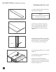
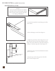
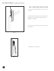
Figure 3
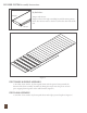
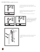
Figure 4
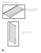
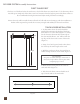
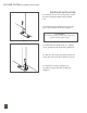
Figure 5
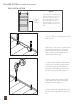
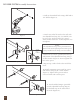
Figure 5A
Alternate
Adjustable
Stop
Installation
6. Drill out the marked holes using a drill with a
1/4” drill bit (Figure 3).
10. Install remaining spacers with lag screws
and washers using a 9/16” socket wrench
(Figure 5). Tighten all lag screws and set
screws if in line with a track spacer.
7. Attach one end of the track to the wall with
one adjustible hard stop (H.) (see NOTE), one
lag screw (B.), and one washer (E.) using a
socket wrench with 9/16” socket (Figure 4). Do
not tighten.
9. Repeat step 7 and 8 for the other end of the
track.
11. Stretch rubber bumper (provided)
over the adjustible hard stop. Repeat
for the hard stop on the other end of
the track (Figure 5A).
8. Insert two set screws (provded) into the top
and bottom of the adjustible hard stop using a
an allen wrench (Figure 4). Do not tighten if in
line with a spacer.
NOTE:
e adjustible hard stop can be placed wherever
desired on the track. If placing in line with a spacer,
always install between the lag screw and washer.