5052 Mic Pre / Inductor EQ Serial #: Operations Manual
5052 Mic Pre / Inductor EQ Thank you for your purchase of the 5052 Mic Pre / Inductor EQ. Everyone at Rupert Neve Designs hopes you enjoy using this tool as much as we have enjoyed designing and building it. Please take note of the following list of safety concerns and power requirements before the use of this product. Safety It’s usual to provide a list of “do’s and don’ts” under this heading but mostly these amount to common sense issues.
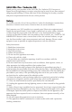
5052: Front Panel 5052 Mic Pre/EQ Mic Pre Mic / Line Selects between mic and line inputs Trim Continuously variable +/6dB trim control 0dB MIC LINE 5051 EQ/Compressor INDUCTOR EQ 48V 0 -6 TRIM +6 LINE 1 LINE 2 TO EQ 36 -15 HF +15 30 22 Level Meters 8 segment LED Meter for monitoring output level 14 10 6 0 4 Mid Parametric Selectable at 200, 350, 700, 1.5 K, 3 K, and 6 KHz. With continuous gain from -15 to +15dB. Selectable Hi Q.
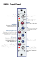
5052: Back Panel MIC IN Mic Input Transformer-balanced XLR mic input selectable on the front panel LINE IN MIC OUT MAIN OUT Line Output Transformer-balanced line level, XLR output. The main output transformer includes the Silk / Texture. EQ IN Mic Out Transformer-balanced XLR line level direct out from the mic pre. Mic out, does not have EQ or Silk. Line Input Transformer-balanced XLR line level inputs selectable on the front panel EQ Input Balanced XLR line level input to the EQ section.
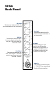
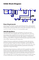
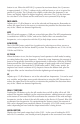
052: Block Diagram CO NT IN UOUS TRIM +/-6dB +IN MI C INPUT OUT PU T STA GE MIC/ L IN E 1 PH A SE 2 INPUT TR ANS FOR MER OUTP UT TR ANS FOR MER HPF ENGA GE MI C OUTPUT 4 G 4 2 1 3 20Hz - 250Hz PH NT M +48VDC 3 T RIM ST E PPE D GA IN 0 - 66dB HPF -IN LI NE INPUT 1 T O EQ 2 L evel Meter 4 3 OUT PU T STA GE EQ NPUT E Q ENGA GE 1 OUTP UT TR ANS FOR MER MAI N OUTPUT 4 2 G 2 1 4 3 TLA T O EQ 3 SIL K RE D/BL UE MID EQ HI & LO SHE L V E S T E X T URE Power Requirements Eac
the output stage. With Silk disengaged, the output is modern and pristine, yet still retains Rupert’s signature larger-than-life transformer sound. The mic pre section also includes a sweepable 20-250Hz high-pass filter, Mic / Line selection, 48V phantom power, and polarity reverse.
MIC PRE DESIGN NOTES FROM MR. RUPERT NEVE In former years, before the introduction of solid state amplifiers, transformers were necessary to step down from the very high input impedance of tubes, and to provide a balanced input for the microphone line.
5052 Features MIC GAIN A 12-way precision rotary switch controls gain from 0 to 66 dB in 6 dB steps. Trim Continuously variable +/-6 dB level control. +48V Engages phantom power on the microphone input. POLARITY Push button inverts the polarity of the signal path, and illuminates when engaged. The symbol “Ø” is often used to denote opposite polarity. MIC / LINE Selects between between the Line and Mic inputs on the back panel of the 5052. EQ IN Engages all bands of the equalizer except the hpf.
button is out. When the MID HI Q is pressed at maximum boost, the Q narrows to approximately 3.5. The Q widens nicely with less boost or cut as is typical for passive EQ circuits. The Q tends to be slightly wider when the frequency is set lower, and slightly higher for higher frequency selections. The Q is also narrower for cuts than it is for boosts and the mid band is non-symmetrical by design. MID LEVEL Adjusts up to 15 dB of boost or cut at the selected mid frequencies.
due to possible converter calibration variables. The 5052 level meter is calibrated for dBu, and the red LEDs may not necessarily match up with the destination device. MIC IN XLR female transformer balanced floating input associated with the Mic position of the front panel input switch. Pin 2 high, 10 k Ohm input impedance. LINE IN XLR female transformer balanced floating input associated with the LINE position of the front panel input switch. Pin 2 high.
aspects to hearing that are beyond the realm of simple traditional measurement characterizations. The way in which an analog amplifier handles very small signals is as important as the way it behaves at high levels. For low distortion, an analog amplifier must have a linear transfer characteristic, in other words, the output signal must be an exact replica of the input signal, differing only in magnitude.
“Temporal resolution of hearing probed by bandwidth restriction”, M. N. Kunchur, Acta Acustica united with Acustica 94, 594–603 (2008) (http://www.physics. sc.edu/kunchur/Acoustics-papers.htm) 3. Miland Kunchur,Depart of Physics and Astronomy, University of South Carolina. Probing the temporal resolution and bandwidth of human hearing , M. N. Kunchur, Specifications Mic Pre Noise Un-weighted, 22Hz-22kHz, source impedance 150 Ohms balanced.
Total Harmonic Distortion and Noise @ 1kHz, +20dBu output level, no load. @ 20Hz, +20dBu output level, no load. Better than 0.002% 0.08% Typical (2nd and 3rd harmonic) Total Harmonic Distortion and Noise with SILK engaged RED TEXTURE @ min @ 100Hz, +20dBu input level, no load TEXTURE @ max @ 100Hz, +20dBu input level, no load 0.015%, mostly 3rd harmonic (typical) 1.
Phantom Power Supplied by internal switching converter. Switch selectable on front faceplate. Maximum input: from 20 Hz to 20 kHz, +25 dBu. Power Requirements @ +/-24VDC maximum current draw 0.26A/0.
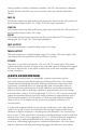
Mid Frequency EQ +20 +15 +10 +5 +0 d B u -5 -10 -15 -20 -25 10 20 50 Sweep Trace Color Comment 1 2 3 4 5 6 7 8 9 1 1 1 1 1 1 1 1 1 Red Magenta Magenta Magenta Magenta Cyan Cyan Cyan Cyan Flat 200 Hz Full Boost 200 Hz Full Boost Hi Q 200 Hz Full Cut 200 Hz Full Cut Hi Q 350 Hz Full Boost 350 Hz Full Boost Hi Q 350 Hz Full Cut 350 Hz Full Cut Hi Q 100 200 500 1k Hz 2k 5k 10k 20k 50k 200k High Frequency EQ +25 +20 +15 +10 d B u +5 +0 -5 -10 -15 -20 -25 10 20 50 100 Sweep Trace Co
PRODUCT WARRANTY Rupert Neve Designs warrants this product to be free from defects in materials and workmanship for a period of one (1) year from date of purchase, and agrees to remedy any defect identified within such one year period by, at our option, repairing or replacing the product.