
User Guide
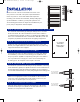

STEP 7 HANG THE TOWEL RADIATOR ON THE WALL
Insert all four radiator posts into the four wall sleeves and tighten
each set screw.
STEP 8 MAKE THE ELECTRICAL OR PIPING CONNECTIONS
Please refer to electrical details or hydronic details below.
HYDRONIC PIPING DET
AILS
ST
EP
9 (HY
DRONIC
MO
DELS
ON
LY
)
Install air vent, (par
t H) and properly seal with pipe dope.
BOTTOM TYPE- VERTICAL PIPING TO FLOOR BOTTOM TYPE- VERTICAL PIPING TO WALL
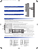
ELECTRICAL DETAILS
Connections for wires is as follows: Black to line, White to neutral, Green to ground
Electrical Installation Procedure:
All electrical towel radiators are designed for 120v AC 60HZ and must be GFCI protected. In the case of plug-in models
this protection is integrated into the cord provided. In the case of the direct wire models, GFIC protection must be
provided at the circuit breaker by a qualified electrician.
To install the direct wire model the electrician should follow these steps:
(1) Remove the two screws on the side of the control unit.
(2) Remove the control unit cover by pulling it forward.
(3) Remove the electrical connection access cover.
(4) Using the appropriate cement, cement Part M into Part N. Leave an 1/8” space
between these parts.
(5) Cut Part O to the required length and cement it to Parts N and P. A strain relief
(provided by the electrician ) is threaded to Part O.
(6) Run the electrical wires through the conduit, secure the strain relief and slide
Par
t M into the slot of the electrical junction box as shown.
(7)
Connect the three wires as
indicated.
(8)
Replace the electrical
connection access cover and
the control unit cover, fasten
in place with two screws.
Location of Conduit:
Starting at the bottom right side of the contr
ol go up 3/4” and over to the left 3/4”. This is
where you drill the hole in the wall to make the connection to the junction box on the unit.
Electrical Connection Access
3 Hour High
Select
Button
Ready Light
Low
Medium
High
Lights
14/2
Solea Installation Sheet.Q6 6/14/07 8:37 AM Page 3