
Install Instructions


Mounting & Installation
Runtal noRth ameRica, inc. US Tel: 800-526-2621 s Canadian Tel: 888-829- 4901 s www.runtalnorthamerica.com
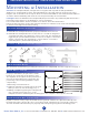
step 1 De t e R m i n e W i R i n g :
2
IMPORTANT INSTRUCTIONS READ & SAVE THESE INSTRUCTIONS
1. Runtal Electric OmnipanelII must be properly installed before it is used.
2. Runtal Electric OmnipanelII comes in two versions: one with an integrated
on/off switch and the other without a control on the unit. The unit with the
toggle may be operated without further accessories or may be connected to
a timer or thermostat. The unit without a control must be connected to
a switching device, thermostat/relay switch, etc.
im p o R ta n t op e R at i n g in s t R u c t i o n s
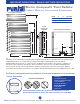
Overview: The OmnipanelII (OPII) is designed for a very quick and easy wall mounting installation.
Simply choose an appropriate location, attach wall brackets to the wall, make the electrical connection,
hang the unit on the wall on the four posts. Please note that all installations of the Runtal OPII should be in
accordance with local building and electrical codes and performed by a licensed installer.
Locating the OPII: The Runtal Electric OmnipanelII (OPII) is intended to be permanently wall mounted in a
horizontal position (Please see the drawing for correct orientation.)
It is recommended that the OPII be mounted no less than 2” above the finished floor.
Inspect the desired location for the OPII and insure that there is sufficient room for the unit and that there are
no obstacles that might hinder wall mounting.
The electrician should start by providing the wiring to the OmnipanelII , use wire rough-in from page 1.
step 2 ma k e a te m p l at e
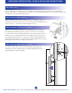
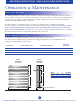
step 3 De t e R m i n e W a l l co n s t R u c t i o n :
For proper installation, the placement of wall
brackets, the electrical hook-up must be exact.
The diagrams at the right show the placement of
the four mounting brackets for all models. The
positioning of the mounting hardware may be
completed by:
1. Measuring out the dimensions
2. Asking an assistant to hold the unit to the wall
while you trace the four mounting posts, or
3. Making a template by placing the Omnipanel II
onto a posterboard or large piece of the
Omnipanel II carton and tracing the mounting posts. The template is then taped to the wall.
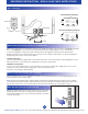
OP2-12
Drill Holes
O
N
O
F
F
OP II-9
Drywall construction may require metal wall anchors (part B). Solid wood or placement directly onto
blocking will require only the #8 x 1
1
/
2
”
long screws (part A). Omnipanels are very sturdy construction,
and care should be taken that they are properly and securely hung using all four mounting points.
A
(4 ea)
B
(4 ea)
C
(4 ea)
D
(4 ea)
E
(1 ea)
Part F
(4 ea)
Part G
(4 ea)
Part H
(1 ea)
Part I
(1 ea)
Part J
(1 ea)
co n t e n t s o f mo u n t i n g ha R D W a R e pa c k a g e
O
N
O
F
F
Integrated on/off switch.
1
1
⁄4”
1
1
⁄2
”
Dia.
12”
C
L
C
L