
User's Manual


Installing the RNU4000BS BS RNU4000BS Base Station User Manual
36 Runcom Technologies Ltd.
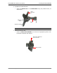
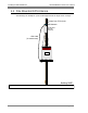
Attach the Bracket Arm to the WALL/POLE BRACKET using the provided
screws.
Note: The bolt head should be positioned in the ARM socket.
Use a tightening torque of 24 N/m to the azimuth and elevation hardware.
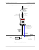
4.2 Overview of the Cable and Power Connections
This section provides a summary of the cable connections. Mounting and connections are
described in detail in the following sections.
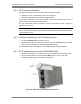
BS Connections:
ATTENTION!!! BE SURE THE RF ANTENNAS ARE CONNECTED OR THE RF
PORTS ARE TERMINATED BEFORE CONNECTING POWER TO THE UNIT.
RF Antennas: (For models with external RF antennas). Connect coax cables from each
RF antenna to the base station ports ANT1/ANT2/ANT3/ANT4.
GPS Antenna: Connect a coax cable (10 meters max) from the GPS antenna to the
BS GPS connector.
Ground: Use the provided grounding cable to ground the BS to the pole (if pole is
grounded), or to a grounding point.
Power: Run the 5-10 meter power cable from the BS Power connector down the pole,
to the provided 48 V power converter that is located indoors (i.e. in a building or in a
caravan).
Note: It is recommended to connect a battery (for backup) to the 48VDC power supply.
Ethernet: Run the 5-10 meter Ethernet cable of the base station from the ETH
connector at the bottom of the base station down the pole and connect it to an indoor
Ethernet connector, such as in a building or in a caravan
ARM
WALL/POLE BRACKET