
User's Manual

Introducing the PicoPlus BS PicoPlus Base Station User Manual
2 CONFIDENTIAL Runcom Technologies Ltd.
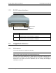
1.1 PicoPlus Interfaces and Accessories
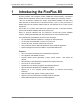
The interfaces of the PicoPlus BS are distributed over two panels. Each of these panels is
referred to according to the corresponding interfaces.
NOTE: Install the BS so the power, GPS and communication interfaces face DOWN.
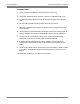
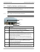
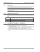
1.1.1 GPS, Power and Communication Interfaces
NOTE: Install the BS on the wall or pole with this panel facing DOWN.
Connector Description
GPS
Connects to an external (optional) GPS antenna. The GPS antenna is ordered
separately. Connector Type: ITT CANNON APD DIN 72585
ETH1
Primary Fast Ethernet connector. Used for initial setup (and standalone tests),
and for connection to the backhaul network (in normal installations).
Connector Type: RJ-45 TYCO part no 1546907-1
ETH2 Second Ethernet port for local and out-of-band management.
In future versions, you will be able to daisy-chain this port to ETH1 in an
adjacent Base Station (located in the same BS site) in order to allow a single
Ethernet connection to the Backhaul.
ETH2 port can also function as a serial port (connection through the cable
supplied in the kit). This function is useful if the unit is not accessible via an IP
address connection.
PPS
PPS In and PPS Out can be used for synchronization of multiple sectors, where
the PPS Out of one sector is connected to the PPS In of the next BS (daisy
chained). This is relevant only for adjacent sectors at the same BS site.
Connector Type: SMA sealed Industrial
-48VDC
Power connector. External DC power connector (-48VDC) for outdoor
deployment. Connector Type: RJ-45
GND
Ground blind hole connector. In normal installations, connect to the pole on
which the unit is mounted. (The BS unit does not include a lightning arrester.)
VDC
Ground
Eth ports
GPS
PPS (In/Out)