
User's Manual

RNU4000BS Base Station User Manual
12 Runcom Technologies Ltd.
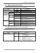
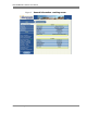
Monitoring screen –The figures below represent the “Monitoring” working screensand provides the next info as
described in the table below:
Menu Section Description
Monitoring Status Synchronization Provides the BS synchronization operational and configuration
status:
• 1PPS lock status– “Lock” or “Unlock” indicates
the 1PPS BS GPS synchronization status
• Modem status – indicates the BS RF status:
- “running” BS RF activated / normal BS operation
- “Not running” BS RF inactivated / BS is not
operational, management is available
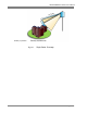
• 1PPS source – indicates the 1PPS source
configuration (see figure “1PPS synchronization
source configuration” below)
- “GPS via Antenna” default configuration
• Physical connection status – “Connected” or “Not
Connected”- indicates physical connection status of BS
external connectors “1PPS input” or “GPS”
• GPS lock status – “Lock” or “Unlock” indicates
the BS GPS lock status
• GPS initialization status – “Initialized” or “Failed”
indicates the BS GPS initialization status
• Hold over time – “0sec to 14400sec indicates the
time of Hold over timer. The timer starts once the BS GPS
loss the 1PPS synchronization “Unlock”
- “14400 sec” default
• Hold over time expired – “Not expired” or
“expired” indicates the Hold over timer status
- Once the timer is expired (14400sec), the BS RF becomes
inactivated and that is in order to prevent interference to other
BS’s.
• Sync change state counter – counting indicates
the BS GPS 1PPS synchronization “unlock” states number “
Radio Status Provides BS sector configuration status info:
• Max DL Modulation
• Max DL Modulation
• Initial Noise – BS receiver initial noise indicates
spectrum radio channel quality of the BS working frequency
Note: Desirable is to obtain initial noise figure less than -
117dbm
• Initial TX power
WiMAX Connection Provides BS connection status info:
• BS ID – indicates the BS ID
• Frequency – indicates the BS central working
frequency
• Bandwidth Profile – indicates the radio BW and
the TX/RX symbols ration
• Preamble ID – indicates the BS preamble ID
• No. connected UT’s – indicates the quantity of
connected CPE’s to the BS
• No. of known NBR Bases – Handover feature /
indicates the quantity of recognized by BS other neighbor
BS’s
Note: N/A for current BS WEB GUI version