OWNER’S OPERATING MANUAL VX-2c Digital Light Processing Projector and DHD Controller
TABLE OF CONTENTS Introduction ..................................................................................................................................................... Warnings & Safety Precautions ..................................................................................................................... Limited Warranty ........................................................................................................................................... Projector Description ....
INTRODUCTION » Introduction to the Runco Video Xtreme™ VX-2c 3-Chip DLP Projector Runco steps into the future once again with the Video Xtreme™ VX-2c projection system. The VX-2c is among the first DLP™ projectors to offer a 16:9 native resolution, 3-chip system for home theater. The VX-2c optical light engine utilizes three of Texas Instruments’ advanced HD-2 DMD’s™ featuring 1280 x 720 high definition resolution and 12 degree mirror tilt for the finest black level performance.
WARNINGS & SAFETY PRECAUTIONS WARNING FCC Regulations state that any unauthorized changes or modifications to this equipment not expressly approved by the manufacturer could void the user’s authority to operate this equipment. CAUTION: TO PREVENT FIRE OR SHOCK HAZARDS, DO NOT REMOVE COVER. DO NOT EXPOSE THIS UNIT TO RAIN OR MOISTURE. ALSO DO NOT USE THIS UNIT’S POLARIZED PLUG WITH AN EXTENSION CORD RECEPTACLE OR OTHER OUTLETS, UNLESS THE PRONGS CAN BE FULLY INSERTED.
WARNINGS & SAFETY PRECAUTIONS DECLARATION OF CONFORMITY RUNCO PROJECTOR, MODEL VX-2c This device complies with Part 15 of the FCC rules. Operation is subject to the following conditions: (1) This device may not cause harmful interference, and (2) this device must accept any interference received, including interference that may cause undesired operation. WARNING Some IC chips in this product include confidential and/or trade secret property belonging to Texas Instruments.
LIMITED WARRANTY Congratulations on your purchase of a Runco video product and welcome to the Runco family! We believe Runco produces “The World’s Finest Home Theater Products”. With proper installation, setup and care, you should enjoy many years of unparalleled video performance. Please read this consumer protection plan carefully and retain it with your other important documents. This is a LIMITED WARRANTY as defined by the U.S. Consumer Product Warranty and Federal Trade Commission Improvement Act.
LIMITED WARRANTY TO OBTAIN SERVICE, CONTACT YOUR RUNCO DEALER: Repairs made under the terms of the Limited Warranty covering your Runco International video product will be performed at the location of the product, during usual working hours, providing location of product is within normal operating distance from a Runco Authorized Service Center.
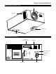
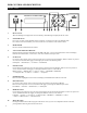
PROJECTOR DESCRIPTION PROJECTOR ISOMETRIC VIEW Lens Intake Vent Exhaust Vent Input Panel PROJECTOR REAR PANEL Vacuum Fluorescent Display DVI Input Power Button and Status LED AC Main Switch Control Panel AC Power In 7
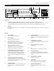
DHD CONTROLLER DESCRIPTION FRONT PANEL 1 8 2 3 4 5 6 7 8 9 10 1. RUNCO ICON When the Red light is displayed the unit is in Standby, when Blue light is displayed the unit is On. 2. POWER BUTTON Press once to toggle on from Standby mode to On mode, a second time to place into Standby mode. For a discreet on or off command, you can use the direct access buttons on the remote control. 3. IR RECEIVER Receives the IR commands from the remote. 4.
DHD CONTROLLER DESCRIPTION REAR PANEL 5 6 11 13 SYSTEM CONTROL INTERFACE INPUTS Serial No Pr R Y G Pb B V TRIGGERS 2 1 Y G CAUTION: TO REDUCE THE RISK OF ELECTRIC SHOCK, DO NOT REMOVE COVER. NO USERSERVICEABLE PARTS INSIDE. REFER SERVICING TO QUALIFIED SERVICE CENTER.
REMOTE CONTROL DESCRIPTION (1) ON/OFF Switches Power ON/OFF. (This does not operate when POWER/STANDBY indicator of the main unit is off.) 1 2 (2) IR OUTPUT INDICATOR Illuminates when a button in pressed, indicating that an IR signal is being transmitted. (3) ENTER BUTTON When an item is highlighted on a menu, pressing ENTER will select that item. (4) CURSOR (▲ / ▼ / ◄ / ►) Use these buttons to select items or settings and to adjust settings or switch the display patterns.
QUICK SETUP GUIDE The VX-2c is designed to receive only digital input signals directly from the companion DHD Controller/Processor. All signal sources should be connected to the appropriate inputs on the rear panel of the DHD. The signal from the DHD is then output to the VX-2c projector through a Runco Proprietary (RP) DVI cable. Please note that it is NOT POSSIBLE to connect a signal source with DVI output directly to the VX-2c. It MUST be routed through the DHD for proper operation.
QUICK SETUP GUIDE Follow the steps below ensure proper installation of the VX-2c projector and DHD Controller. Step I Connection: 1. Connect Power to Both Projector and DHD controller 2. Connect DVI output from the DHD to projector DVI in 3. Connect Video (Composite), S-Video to1 or 2, Component 480i (RCA) input, HD signals to HD1 or HD2 (BNC), DVI 4. Turn ON the system from the DHD controller or use the DHD remote. Step II From the Projector: 1. Press Menu to select Main window.
QUICK SETUP GUIDE While there are many different ways to connect your source equipment to your DHD Controller, the examples below are the most common. ANALOG INPUTS: • Composite Video Input Composite video is the most common type of signal used, but is also the lowest in picture quality. Many sources have outputs that are limited to composite video, such as some VCR’s and camcorders; others such as Laser Disc players actually produce slightly better results when using composite video.
LENS SHIFT RANGE Lens Option 1: Throw Distance 1.2 - 1.4 x Width of Screen When only Vertical or only Horizontal Shift is used: Maximum. Vertical Shift ↑ = 60% of screen height (.60 x height) Maximum. Vertical Shift ↓ = 24% of screen height (.24 x height) Maximum Horizontal Shift = 10% of screen width (.10 x width) Amount of Horizontal Shift when Vertical is @ maximum: Maximum Horizontal Shift < 5% of screen width (.
LENS SHIFT RANGE Lens Option 4: Throw Distance 2.35 - 3.60 x Width of Screen When only Vertical or only Horizontal Shift is used: Maximum. Vertical Shift ↑ = 60% of screen height (.60 x height) Maximum. Vertical Shift ↓ = 24% of screen height (.24 x height) Maximum Horizontal Shift = 16% of screen width (.16 x width) Amount of Horizontal Shift when Vertical is @ maximum: Maximum Horizontal Shift < 5% of screen width (.
LENS SHIFT RANGE Example of Horizontal and Vertical Lens Shift VERTICAL LENS SHIFT (UP OR DOWN) Note: This is a general example of Vertical Lens Shift. Each lens type will vary. No particular lens was used in this example.
MENU DESCRIPTION AND NAVIGATION » PROJECTOR CONTROL Once the VX-2c and DHD controller have been properly installed and connected, you are ready to perform set-up and calibration procedures. All setup and calibration parameters are accessed and adjusted through the VX-2c fluorescent display menu system. The VX-2c/DHD system has been designed to incorporate setup and calibration standards established by the Imaging Science Foundation (ISF).
MENU DESCRIPTION AND NAVIGATION MAIN MENU MAIN MENU Main Menu Wt. Balance Orient Lens Adj. Proj. Info Advanced Wt. Balance Orient Opening screen Press ENTER to access the White Balance Settings menu Press ENTER to access the Orientation Setting menu Lens Adj. Proj. Info Advanced Press ENTER to access the Lens Adjustment setting menu Press ENTER to access the Projector Status menu Press ENTER to access the Advanced Settings menu This is the first menu that will appear when “MENU” is selected.
MENU DESCRIPTION AND NAVIGATION Orient Orient Preference Orient Indicates you are on the Preference Settings menu Press ENTER to select the Orientation setting menu Use Preference window to select projector picture orientation From the Main menu use the Up or Down arrow to select “Orient” and press the Enter button to call up the Orient display. The Orient display allows selection of Picture Orientation options. There are four options: Floor F.: Floor Front configuration. Ceiling F.
MENU DESCRIPTION AND NAVIGATION Proj. Info Model S/N Hardware Revision Firmware Revision Error Code Proj. Info Model S/N Hardware Revision Firmware Revision Error Code Indicates you are on the Status reading menu Reports the Projector Model Reports the Projector Serial Number Reports the Projector Hardware Revision number Reports the Projector Firmware Revision number Reports the last Projector Error Code received From the Main menu use the Up or Down arrow to select “Proj.
MENU DESCRIPTION AND NAVIGATION OPERATIONAL INSTRUCTIONS Gain Red Green Blue Gain Red Green Blue Indicates you are in the Contrast Setting Menu Press ENTER to change the Red Contrast setting by using the UP and DOWN arrows to Increase or Decrease the value Press ENTER to change the Green Contrast setting by using the UP and DOWN arrows to Increase or Decrease the value Press ENTER to change the Blue Contrast setting by using the UP and DOWN arrows to Increase or Decrease the value From the Image menu us
MENU DESCRIPTION AND NAVIGATION Gamma Red Green Blue Gamma Red Green Blue Indicates you are in the Gamma Setting Menu Press ENTER to change the Red Gamma setting by using the UP and DOWN arrows to Increase or Decrease the value Press ENTER to change the Green Gamma setting by using the UP and DOWN arrows to Increase or Decrease the value Press ENTER to change the Blue Gamma setting by using the UP and DOWN arrows to Increase or Decrease the value From the Image menu use the Up or Down arrow to select “G
MENU DESCRIPTION AND NAVIGATION Diagnose Normal Color Enable Tests Diagnose Normal Color Enable Tests Indicates you are in the Diagnostics menu Press ENTER to return all Diagnostic Tests to their Normal mode Press ENTER to individually Enable each Color Press ENTER to access External front end board and Internal DLP Test Modes From the Advanced menu use the Up or Down arrow to select “Diagnose” and press the Enter button to call up the Diagnose options.
MENU DESCRIPTION AND NAVIGATION Color Gamut Color Space Color Temp Color Gamut Color Space Color Temp Indicates you are in the Color Settings menu Press ENTER to access the Gamut settings menu Press ENTER to access the Color Space settings menu Press ENTER to access the Color Temperature setting menu From the Advanced menu use the Up or Down arrow to select “Color” and press the Enter button to call up the Color options.
MENU DESCRIPTION AND NAVIGATION Color Enable Red Green Blue Yellow Cyan Magenta Color Enable Red Green Blue Yellow Cyan Magenta Indicates you are in the Color Enable menu Press ENTER to turn Red On Press ENTER to turn Green On Press ENTER to turn Blue On Press ENTER to turn Red Off Press ENTER to turn Blue Off Press ENTER to turn Green Off From the Diagnose menu use the Up or Down arrow to select “Color Enable” and press the Enter button to call up the Service options.
MENU DESCRIPTION AND NAVIGATION Tests Test Black Test White Test Green Test Red Test Blue Check Board Alignment H Ramp V Ramp Tests Indicates you are In the Internal DLP Test mode Test Black Test White Test Green Test Red Test Blue Check Board Alignment H ramp V ramp Press ENTER to display a full Black screen Press ENTER to display a full White screen Press ENTER to display a full Green screen Press ENTER to display a full Red screen Press ENTER to display a full Blue screen Press ENTER to display a Ch
MENU DESCRIPTION AND NAVIGATION Color Space HD SD NTSC SD PAL Color Space HD SD NTSC SD PAL Indicates you are in the Color Space setting menu Press ENTER to select the HD Color Space Press ENTER to select the SD NTSC Color Space Press ENTER to select the SD PAL Color Space From the Color menu use the Up or Down arrow to select “Color Space” and press the Enter button to call up the Service options. Use the Up or Down button to indication your selection and press the Enter button to make your selection.
MENU DESCRIPTION AND NAVIGATION Manual White Red Green Blue Manual White X=0.XXX White Y=0.YYY Red X=0.XXX Red Y=0.YYY Green X=0.XXX Green Y=0.YYY Blue X=0.XXX Blue Y=0.YYY Indicates you are in the Manual Gamut setting mode using a calibrated colorimeter.
BASIC TROUBLESHOOTING TIPS The following is a basic troubleshooting guide that can assist you in resolving typical problems may result in normal operation. If you have encountered problems that are not listed in this guide, please contact your Runco dealer for assistance. PROBLEM POSSIBLE CAUSE SOLUTION The Projector does not turn on after initial installation. The Power LED on the front of the Controller stays red after the power button is pressed.
RS-232 COMMUNICATIONS Baud rate: 19200 (fixed) Bits: 8 No Parity All protocol in ASCII format RS-232 input connector pin numbers: TxD= Pin# 2, RxD= Pin# 3, GnD= Pin# 5 Command format (single command): command value (i.e. brightness 100). NOTE: A space (not an underscore) or comma may be used between the command and its value. Command string format: command, command value, command etc. (i.e.
RS-232 COMMANDS Command Parameter (min/max) Value Stored? Description POWER ON OFF COMPOSITE SVIDEO1 SVIDEO2 COMPONENT HD1 HD2 DVI1 DVI2 HD1Pass HD2Pass OUT43 OUT169 ANAMORPHIC STANDARD LETTERBOX VIRTUALWIDE RGBNN RGBPP RGBS YUV IHPOS IVPOS IWIDTH IHEIGHT OVERSCAN OHPOS OVPOS OWIDTH OHEIGHT BRIGHTNESS CONTRAST COLOR TINT SHARPNESS NIGHT DAY CUSTOM1 CUSTOM2 TRIGGER BKGND 0/1 NA NA NA NA NA NA NA NA NA NA NA NA NA NA NA NA NA NA NA NA NA NA -100/100 -100/100 -100/100 -100/100 0/10 -100/100 -100/100 -100/
RS-232 COMMANDS 32 Command Parameter (min/max) Value Stored? Description IHPOS? IHEIGHT? OHPOS? OHEIGHT? COLOR? ASPECT? INPUT? OUTRES? SERIALNUM? DATE? IVPOS? OVERSCAN? OVPOS? BRIGHTNESS? TINT? PRESET? POWER? ASPECTIN? SWVER? IWIDTH? PHASE? OWIDTH? CONTRAST? SHARPNESS? BKGND? INRES? ASPECTOUT? HWVER? NA NA NA NA NA NA NA NA NA NA NA NA NA NA NA NA NA NA NA NA NA NA NA NA NA NA NA NA NA NA NA NA NA NA NA NA NA NA NA NA NA NA NA NA NA NA NA NA NA NA NA NA NA NA NA NA Returns input horizontal position
SPECIFICATIONS VX-2c PROJECTOR SPECIFICATIONS Projector Type: Digital Light Processing™ (DLP™), 3-chip, 16:9 HD-2, DMD™ Native Resolution: 1280 x 720 (16:9) Aspect Ratios: Determined by supplied processor Video Standards: Determined by supplied processor DTV Compatibility: Determined by supplied processor Scan Frequency: Horizontal: 15 – 100 KHz Vertical: 28 – 78 Hz Recommended Width: 72 – 120 in. Maximum Width: 250 in. Lens Option 1: Zoom 1.20–1.40 x width Lens Option 2: Zoom 1.40–1.
SPECIFICATIONS DHD™ DIGITAL CONTROLLER SPECIFICATIONS Aspect Ratio: Anamorphic, Letterbox, VirtualWide, 4:3 (on either 16:9 or 4:3 screens) Input Standards: NTSC/PAL Output Resolution: 720P Outputs: (1) HD - R (Pr), G (Y), B (Pb), H, V; (1) DVI w/HDCP Inputs: Screen Trigger/Masking Outputs: (1) Composite, (2) S-Video, (1) Component (480i or 576i), (2) RGBHV/Component HD, (2) DVI Digital w/HDCP Discrete infrared remote, (2) RS-232, (1) 9-pin connector, (1) RJ-11, Front panel controls (3) 12V DC, 1
RUMA-010120 8-6-04 v5.