
- RUNCO International OWNER'S OPERATING MANUAL 1080p Digital Light ProcessingTM Projector and Digital High Definition (DHDTM) Controller VX-44d, VX-55d
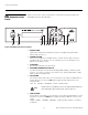
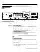
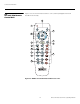
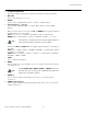

Table Of Contents
- TWO YEAR LIMITED WARRANTY
- Safety Precautions
- 1. Introduction
- 2. Controls and Functions
- 3. Installation
- 3.1 Remote Control
- 3.2 Quick Setup
- 3.3 Installation Considerations
- 3.4 Installing the Projection Lens
- 3.5 Installing the Optional CineWide Lens Mount
- 3.6 Mounting the VX-44d/-55d
- 3.7 Connections to the VX-44d/-55d and DHD Controller
- Connector Panel Access
- Connecting the DHD Controller to the VX-44d/-55d
- Connecting Source Components to the DHD Controller
- RS-232 Controller Connection
- Connecting 12-Volt Trigger Outputs to External Theater Equipment
- Connecting an External IR Receiver to the DHD Controller
- Connecting to AC Power
- 3.8 Turning on the Power
- 3.9 Adjusting the Picture Orientation
- 3.10 Primary Lens Adjustments
- 3.11 Installing and Adjusting the CineWide Anamorphic Lens
- 3.12 Calibrating Projector Input 2 (DVI)
- 3.13 Working With the Lamp
- 4. Operation
- 5. Maintenance and Troubleshooting
- 6. Serial Communications
- 7. Specifications

Controls and Functions
12 Runco VX-44d/-55d Owner’s Operating Manual
PRE
L
IMINAR
Y
2.5
DHD Controller Rear
Panel
Figure 2-5 shows the rear connector panel on the DHD Controller.
Figure 2-5. DHD Controller Rear Panel
Outputs 1. HDMI OUT
Connect this to Input 2 (DVI) on the VX-44d/-55d (see Figure 2-2).
Inputs 2. HDMI 1 / HDMI 2 (Digital)
Two, HDCP-compliant digital video inputs for connecting a DVD player or HD tuner
with a DVI or HDMI output.
3. HD1 / HD2 (5 x Analog BNCs)
Two inputs (five BNCs per input) for connecting either RGB or component
high-definition television signals. The DHD Controller automatically detects the signal
format: RGB(HV) or YPrPb, 480p, 720p, 480i, 576i or 1080i.
4. COMPONENT VIDEO (RCA connectors)
Standard Definition (480i/576i) Component (YPrPb) input. This is the input for
component video from sources such as DVD players.
5. COMPOSITE VIDEO INPUT
Standard composite video input for connecting a VCR, laser disc player or other
composite video source.
6. S-VIDEO 1 / S-VIDEO 2
Two, standard S-Video inputs for connecting a DVD player, satellite receiver or Super
VHS (S-VHS) VCR.
7. 12-VOLT (750 mA) TRIGGER OUTPUTS
Connection for up to three (3), 12-volt trigger-controlled devices such as retractable
screens or screen masks.
Pb Pr Y
Video
3
IR
RS-232 Control
S-Video 1
S-Video 2
HD1
HD2
1
2
R/Pr G/Y B/Pb
R/Pr G/Y B/Pb H V
HDMI 1 HDMI 2HDMI Out
HV
TRIGGERS
RS-232 Out
CAUTION:
TO REDUCE THE RISK OF ELECTRIC
SHOCK, DO NOT REMOVE COVER. NO USER-
SERVICEABLE PARTS INSIDE. REFER SERVICING
TO QUALIFIED SERVICE CENTER.
AVI S: RISQUE DE CHOC ELECTRIQUE-NE PAS OUVRIR
CAUTION
RISK OF ELECTRIC SHOCK
DO NOT OPEN
!
WARNING:
TO REDUCE THE RISK OF FIRE
OR ELECTRIC SHOCK, DO NOT EXPOSE
THIS APPLIANCE TO RAIN OR MOISTURE.
100-230VAC 50-60 Hz, 165 Watts Max
INPUTS
SYSTEM CONTROL INTERFACE
Component Video
Serial No
Video Processor / Controller
Model
Made In USA
1
2
4
5
10
11
12 13
8
6
79
3
➤
➤
For best results, do not run your DVD player in progressive mode.
Tip