
Specifications


Table Of Contents
- TWO YEAR LIMITED WARRANTY
- Safety Precautions
- 1. Introduction
- 2. Controls and Functions
- 3. Installation
- 3.1 Remote Control
- 3.2 Quick Setup
- 3.3 Installation Considerations
- 3.4 Installing the Projection Lens, Lamp and Cooling
- 3.5 Installing the Optional CineWide Lens Mount
- 3.6 Mounting the SC-1
- 3.7 Connections to the SC-1 and DHD Controller
- Input Panel Access
- Connecting the DHD Controller to the SC-1
- Connecting Source Components to the DHD Controller
- RS-232 Controller Connection
- Connecting 12-volt Trigger Outputs to External Equipment
- Connecting an External IR Receiver to the DHD Controller
- Connecting an External Power Supply/Ballast to the Projection Head
- Connecting to AC Power
- 3.8 Turning on the Power
- 3.9 Maximizing Light Output
- 3.10 Adjusting the Picture Orientation
- 3.11 Primary Lens Adjustments
- 3.12 Installing and Adjusting the CineWide Anamorphic Lens
- 3.13 Calibrating Projector Input 2 (DVI)
- 3.14 Working With the Lamp
- 4. Operation
- 5. Maintenance and Troubleshooting
- 6. Serial Communications
- 7. Specifications
Installation
Runco SC-1 Owner’s Operating Manual 49
PRE
L
IMINAR
Y
3.12
Installing and
Adjusting the
CineWide Anamorphic
Lens
If you are installing a CineWide-equipped projector, proceed as follows to install and
adjust the anamorphic lens.
The SC-1 Anamorphic lens mount kit consists of everything shown in Figure 3-27. Some
components shipped with your projector may differ slightly from what is shown in these
instructions. If any items are missing or damaged, please contact your Runco dealer or
Runco Customer Service at (800)
23-RUNCO.
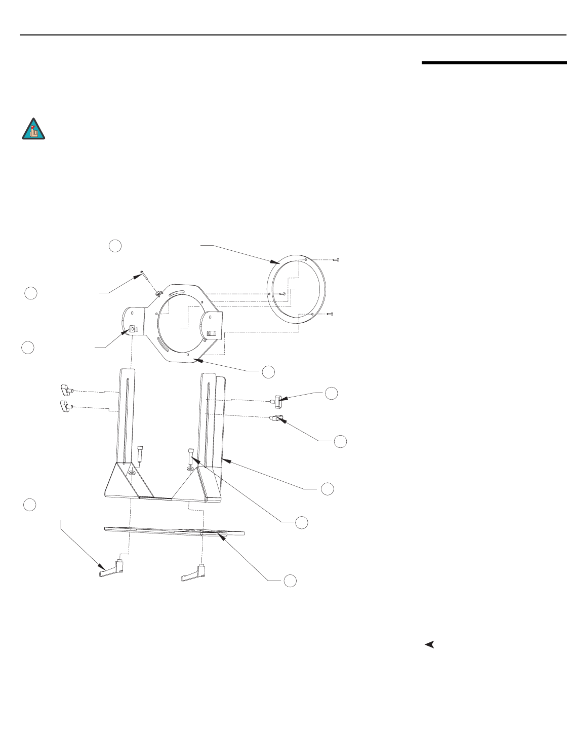
Figure 3-27. Anamorphic Lens Mouning Assembly - Exploded View
Attach Lens Mounting
Assembly to Lens Motor
Carriage Plate
1. Remove the two Yaw/X Adjustment Levers (item #8) from the bottom of the
Anamorphic Lens Holder (item #5).
2. Place the Anamorphic Lens Holder on top of the AutoScope Carriage Plate (item #7).
Position the bracket so that the long slot at the bottom of the lens holder is
perpendicular to the corresponding slots on the carriage plate.
It is extremely important that the primary lens is properly
adjusted before you install the anamorphic lens. Ensure that
the image from the primary lens is perfectly centered on the
screen.
Note
2
3
4
6
7
8
5
1
9
Pitch Adjustment Yoke for Lens
Height/Y Adjustment
T-Screw (2x)
T-Screw (2x)
Pitch Adjustment
Anamorphic Lens
Holder
1/4-20 Hex Bolt (2x)
and Washer (2x)
AutoScope Carriage Plate
Yaw/X Adjustment
Lever (2x)
Lens Adapter Ring and
Mounting Screws (3x)
Pitch Adjustment
T-Nut (2x)
10
Anamorphic Lens
Set Screw