I NSTALLATION/ O PERATION M ANUAL LS-10d DLPTM Home Theater Projector and Digital High Definition (DHD™) Controller/Scaler/Processor
RuncoCare™ Standard Two Year Limited Warranty Congratulations on your purchase of a Runco® product! With proper installation, setup and care, you should enjoy many years of unparalleled video performance. Y This RuncoCare Standard Limited Warranty is provided free of charge by Runco International, LLC (“Runco”) with the purchase of a covered Runco product.
RuncoCare Claim Procedure In the event of a product defect, please follow the warranty claim procedure provided below: 1. The Customer is required to contact a Runco dealer or Runco Technical Support via email at support@runco.com or via phone at (toll free) (800) 23RUNCO (800-237-8626). If the customer is located outside North America, call +3589 4200 554 in Europe for product service. 2.
h Expected lamp degradation and normal decrease in lamp output over a period of time or as the lamp is consumed i Customer caused defects, including but not limited to, scratched/defaced/altered plastics j Failure to follow maintenance procedures as outlined in the product’s user guide where a schedule is specified for regular cleaning of the product k Opening the product and/or tampering with internal circuitry l Products lost, stolen or discarded m Any damage or dissatisfaction associated with laten
Online Product Registration Please visit http://www.runco.com/support/product-registration/ to register product. Limitation of Implied Warranties Y RUNCO PROVIDES NO WARRANTIES, EXPRESS OR IMPLIED, EXCEPT THOSE EXPRESSLY PROVIDED HEREIN. RUNCO EXPRESSLY DISCLAIMS ALL OTHER WARRANTIES, INCLUDING THE IMPLIED WARRANTIES OF MERCHANTABILITY AND FITNESS FOR A PARTICULAR PURPOSE.
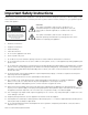
Important Safety Instructions Thank you for your purchase of this quality Runco video product! It has been designed to provide you with the quality of video that is expected in a home theater. For the best performance, please read this manual carefully as it is your guide through the menus and operation. 1. Read these instructions. 2. Keep these instructions. 3. Heed all warnings. 4. Follow all instructions.
19. Never look directly into the lens when the lamp is on.
FCC PART 15: NOTE: This equipment has been tested and found to comply with the limits for a Class B digital device, pursuant to Part 15 of the FCC Rules. These limits are designed to provide reasonable protection against harmful interference in a residential installation. • Reorient or relocate the receiving antenna. EL IM IN A R • Increase the separation between the equipment and receiver.
PR EL IM IN A R Y Notes: x Runco LS-10d Installation/Operation Manual
1 Table of Contents RuncoCare™ Standard Two Year Limited Warranty ................................................... iii Important Safety Instructions ....................................................................................... vii Compliance Information .............................................................................................. viii 1. Introduction ...............................................................................................................
Table of Contents Installing the Optional Anamorphic Lens Mount ..........................................................23 Package Contents ................................................................................................23 Mounting the LS-10d .................................................................................................28 Floor Mounting (Upright) .......................................................................................28 Ceiling Mounting (Inverted)........
Table of Contents 5. Maintenance and Troubleshooting ........................................................................73 Lamp Replacement ....................................................................................................73 Troubleshooting Tips ..................................................................................................74 6. External Control ......................................................................................................
Table of Contents PR EL IM IN A R Y Notes: xiv Runco LS-10d Installation/Operation Manual
1 List of Figures 2-1. LS-10d Front/Side View ...............................................................................................5 2-2. LS-10d Rear/Bottom/Top View ....................................................................................6 2-3. LS-10d Rear Panel .......................................................................................................8 2-4. DHD Controller Front Panel ........................................................................................
List of Figures PR EL IM IN A R Y Notes: xvi Runco LS-10d Installation/Operation Manual
1. Introduction This Owner’s Manual describes how to install, set up and operate the Runco LightStyle™ Series LS-10d Home Theater Projector and DHD Controller. 1.1 About This Manual Y Throughout this manual, the Runco LightStyle™ Series LS-10d Home Theater Projector and DHD Controller are referred to collectively as the “LS-10d.” EL IM IN A R Runco has prepared this manual to help home theater installers and end users get the most out of the LS-10d.
Introduction Graphic Conventions: These symbols appear in numerous places throughout the manual, to emphasize points that you must keep in mind to avoid problems with your equipment or injury: Note NOTES emphasize text with unusual importance or special significance. They also provide supplemental information. Caution CAUTIONS alert users that a given action or omitted action can degrade performance or cause a malfunction.
Introduction The LightStyle™ Series LS-10d Home Theater Projector and DHD Controller encompasses Runco’s award-winning three-chip performance in an elegant, sleek package. Feature rich, including advanced connectivity and the latest-generation video processing, the LS-10d provides style and elegance to the most exacting custom theaters. Y Impressive, unique and unlike single-chip DLP™ implementations, no color wheel is used in the LS-10d.
Introduction Key Features and Benefits ➤ The LS-10d offers these key features and benefits: • Native Resolution: 1920 x 1080 (16:9 Native Aspect Ratio) • Three-chip Digital Light Processing (DLP™) system • Four (4) HDMI 1.3 Inputs (on DHD Controller) with High-bandwidth Digital Content Protection (HDCP) • HDTV Compatible • CinOptx™ Proteus lens options for stunning sharpness and throw distance flexibility Parts List ➤ Your LS-10d is shipped with the following items.
2. Controls and Functions 2.1 LS-10d at a Glance Figure 2-1 and Figure 2-2 show the key LS-10d components. EL IM IN A R Y Status LED System Keypad Exhaust Vent Intake Vent PR Projection Lens Figure 2-1.
Controls and Functions • PROJECTION LENS If needed, a light shield accessory is provided with the lens to minimize stray light emissions. (Use it only when the vertical offset is 50% of the screen height or greater.) The light shield attaches to the end of the lens. EL IM IN A R Y Runco Logo Badge Rear Cover PR Lamp Module Cover Cable Opening Ceiling Mount Holes Adjustable Feet Figure 2-2.
Controls and Functions • RUNCO LOGO BADGE • REAR COVER Remove to access connectors. • LAMP MODULE COVER Remove this cover to access the lamp compartment. • CABLE OPENING Pass cables through this opening. • CEILING MOUNT HOLES Use these to attach the ceiling bracket to the projector. Use M4 screws with a maximum screw depth of 10 mm (0.39 inch).
Controls and Functions 2.2 LS-10d Rear Panel EL IM IN A R Y Figure 2-5 shows the LS-10d rear panel. 1 2 3 Figure 2-3. LS-10d Rear Panel PR 1. DHD INPUT An HDCP-compliant digital video input for connecting the HDMI output from the DHD Controller. 2. TRIGGER 1 Provides 12 (+/- 1.5) volt switched output for an anamorphic lens transport (if installed) with 250mA current capacity and short protection.
Controls and Functions 2.3 DHD Controller Front Panel Figure 2-4 shows the controls and indicators on the DHD Controller front panel; the paragraphs that follow describe them. 11 10 4 2 LS-10d HDMI 1 16:9 1080i/60 Y ratio standby enter i n p u t EL IM IN A R 1 9 3 4 5 6 1. RUNCO ICON Lights blue to indicate that the controller is on or powering up. 2. IR SENSOR Receives IR commands from the remote control. PR 3.
Controls and Functions 7. RIGHT BUTTON Used to direct-select inputs or move the menu cursor right in the OSD. When no menus are present on-screen, the RIGHT button toggles through the different sources, in this order: Composite 1 - Composite 2 - Composite 3 - Component - HD 1 - HD 2 - SCART HDMI 1 - HDMI 2 - HDMI 3 - HDMI 4 8. MENU BUTTON Press the MENU button to bring up the main menu, or to exit the current menu and return to the previous one. EL IM IN A R Y 9.
Controls and Functions 4. RS-232 (To Accessory Box) A male, 9-pin D-sub connector for interfacing with external equipment. (For future use.) 5. Display Control Not used with the LS-10d. 6. IR Wired input from a Niles- or Xantech-compatible, infrared (IR) repeater system. It is a 3.5-mm, mini phono jack, wired as follows: Ring = No connection Tip = IR Input Sleeve = Ground EL IM IN A R Y 7. POWER INPUT (100 to 240 VAC) Connect the DHD Controller to power here. 8.
Controls and Functions 2.5 LS-10d Remote Control Unit Figure 2-6 shows the LS-10d remote control, and the paragraphs that follow describe its functionality. 1 2 LIGHT 3 OFF RATIO 4 I N P U T EL IM IN A R I N P U T Y ON 5 EN T ER 6 RATIO EXIT 8 ISF NT 9 VID 1 10 HD 1 HDMI 1 PR 12 ISF DAY 1 4 7 HDMI 3 14 CUST 1 VID 2 HD 2 HDMI 2 HDMI 4 2 7 MENU CUST 2 VID 3 3 COMP 5 11 6 SCART 8 13 9 NATIVE 0 16 : 9 4:3 LET BOX V-WIDE CINEMA V-CINE Figure 2-6.
Controls and Functions 1. IR OUTPUT INDICATOR Lights when a button is pressed to indicate that an IR signal is being transmitted. 2. LIGHT Press to illuminate the buttons. 3. ON / OFF Press to turn the DHD Controller and projector on or off. 4. ENTER Press to select a highlighted menu item or confirm a changed setting. Y 5. Cursor Buttons ( , , , ) Use these buttons to select items or settings, adjust settings or switch display patterns.
Controls and Functions 10. HD 1 (4) / HD 2 (5) Press to select a HD (RGBHV or YPbPr component) input or to enter the numeric character “4” or “5.” 11. COMP (Component) (6) Press to select the Component video input as the source or to enter the numeric character “6.” 12. HDMI 1 (7) / HDMI 2 (8) / HDMI 3 / HDMI 4 (0) Press to select an HDMI input as the source or to enter the numeric character “7,” “8” or “0.” Y 13.
3. Installation Installation must be performed by a qualified custom video installation specialist. Y Note To install batteries in the remote control: EL IM IN A R 1. Press down the tab on the cover and pull the cover in the direction of the arrow. 3.1 Remote Control 2. Insert the included batteries. Ensure that the polarities correctly match the and markings inside the battery compartment. PR 3. Insert the lower tab of the cover into the opening, and press down the cover until it clicks in place.
Installation 3.2 Quick Setup Table 3-1 gives a quick overview of the LS-10d installation process. The sections following this one provide detailed instructions. Table 3-1. Installation Overview Step For Details, Refer to page...
Installation Proper installation of your projector will ensure the quality of your display. Whether you are installing a projector temporarily or permanently, you should take the following into account to ensure your projector performs optimally. 3.3 Installation Considerations Choose the installation type that best suits your needs: front or rear screen, floor mount or inverted mount. Table 3-2 compares these various installation methods.
Installation Ambient Light ➤ In general, minimize or eliminate light sources directed at the screen. Contrast ratio in your images will be noticeably reduced if light directly strikes the screen, such as when a shaft of light from a window or floodlight falls on the image. Images may then appear washed out and less vibrant. Throw Distance ➤ Throw distance is the distance measured from the front of the projector to the screen.
Installation Table 3-3 lists the available lens options for the LS-10d and their associated throw ratios. Table 3-3. LS-10d Lens Options and Throw Ratios (Note 1) Throw Ratio Lens Option with Primary Lens Only Throw Range in inches, with 96x54-inch (1.78:1) Screen Minimum Throw Range in Throw Ratio inches, with with Primary 126.9x54-inch (2.35:1) Lens and Screen Anamorphic Lens Maximum Minimum Maximum For rear-screen installations only. Contact Runco Technical Support for more information. 0.
Installation Vertical and Horizontal ➤ Position Proper placement of the projector relative to the screen will yield a rectangular, perfectly-centered image that completely fills the screen. Ideally, the projector should be positioned perpendicular to the screen and in such a way that the lens center is aligned with either the top or bottom edge of the screen area, and centered horizontally. See Figure 3-2.
Installation 100% Width Lens Shift (1.0 x W) 50% Width Lens Shift (0.5 x W) Screen Center Y 0% EL IM IN A R Screen Width (W) PR Note: This is a general example of lens shift. Lenses vary in their shift capabilities. No particular lens or projector is used in this example. Figure 3-4. Horizontal Lens Shift (EXAMPLE ONLY) Vertical Lens Shift: The LS-10d zoom lenses (Proteus 2 through 6) provide up to 65% of vertical lens shift in either direction (up or down).
Installation Folded Optics ➤ In rear screen applications where space behind the projector is limited, a mirror may be used to fold the optical path, as shown in Figure 3-5. The position of the projector and mirror must be accurately set. If you are considering this type of installation, contact your dealer for assistance. Screen EL IM IN A R Y Mirror Figure 3-5.
Installation Other considerations and tips that can help improve your installation: Other Considerations • Keep the ambient temperature constant and below 35°C (95°F). Keep the projector away from heating and/or air conditioning vents. Changes in temperature may cause drifts in the projector circuitry, which may affect performance. • Keep the projector away from devices that radiate electromagnetic energy such as motors and transformers.
Installation • Anamorphic lens and mounting bracket Y Attaching the Transport Assembly Attachment Plate: 1. Place the projector upside down on a blanket or other soft surface. EL IM IN A R 2. Position the attachment plate as shown here.
Installation 3. If you are mounting the projector on a ceiling: Line up the holes on the Ceiling Mount Plate (included with the projector ceiling mount kit) with those on the bottom of the projector and attachment plate. 4. Secure the Transport Assembly Attachment Plate and Ceiling Mount Plate to the projector using the hardware provided with the attachment plate, as shown. Caution 1. Do not use the mounting screws provided with the ceiling mounting kit.
Installation Installing the Anamorphic Lens Transport Assembly: After installing the Transport Assembly Attachment Plate and Ceiling Mount Plate, proceed as follows to install the Anamorphic Lens Transport Assembly.
Installation Attaching the Security Hooks: To help stabilize and support the added weight of the Anamorphic Lens and Lens Transport Assembly, the attachment plate includes two security hooks and related hardware for attaching the front part of the plate to the ceiling above. Proceed as follows to attach the security hooks. This requires the following tools and materials: • Pliers • Scissors EL IM IN A R Y • Ceiling Hooks (not supplied) 1.
Installation 3.5 Mounting the LS-10d There are several methods for mounting the projector. Depending on your chosen installation, one method may be more suitable than another. Floor Mounting (Upright) ➤ For fixed installations, and for those that want the projector out of sight or have a limited space for projector and audience, you can invert the LS-10d and suspend it from the ceiling using a specially-designed ceiling mount fixture.
Installation If the LS-10d is ceiling-mounted and the screen is significantly lower than the projector, you can tilt the projector at a slight angle by adjusting the ceiling mount. EL IM IN A R Y The projector can be rotated (side-to-side) up to 360 degrees and mounted without it affecting performance. However, to ensure optimal performance of the lamp, limit the front-to-back tilt of the projector to ±20 degrees; see Figure 3-6. ± 360º ± 20º Figure 3-6.
Installation 3.6 Connections to the LS-10d and DHD Controller Proceed as follows to connect the DHD Controller to the LS-10d, your video sources, external controller(s) – if present – and AC power. When connecting your equipment: • Turn off all equipment before making any connections. • Use the correct signal cables for each source. • For best performance and to minimize cable clutter, use high-quality cables that are only as long as necessary to connect two devices.
Installation Digital Video Connection: Connect the “HDMI Out To Display” connector on the DHD Controller to the DHD Input of the LS-10d as shown in Figure 3-7. Use an HDMI cable for this connection. A DVI cable with DVI-to-HDMI adapters will not work.
Installation Connecting Source ➤ Components to the DHD Controller Connect your video sources to the DHD Controller as shown and described in the sections that follow. HDMI Source Connections: See Figure 3-8. Use the HDMI inputs whenever possible. This ensures the highest video quality because the signal is carried in the digital domain throughout the entire signal path, from source component output into the projector. Tip You can also connect computers with DVI output to these inputs.
Installation Component Video Source Connections: Connect your component video sources to the HD1, HD2 and/or Component/SCART inputs as shown in Figure 3-9. TRIGGERS 1 Y G Pb B Pr R V H 2 Component / SCART Y Video 1 Video 2 Pb Pr Video 3 HD1 HD2 Y G Pb B Pr R H V BD/DVD Y PB PR COMPONENT VIDEO OUT EL IM IN A R Y RCA-to-BNC adapter PR DTV-Set-Top Box (DTV-STB) Figure 3-9.
Installation RGBHV Source Connections: Connect personal computers and/or other RGB sources to the HD1 and/or HD2 inputs as shown in Figure 3-10. Y G Pb B Pr R V H HD1 HD2 Y G Pr R H V V-Sync H-Sync Red Blue Green EL IM IN A R Y Pb B RGB Camcorder Computer PR or Figure 3-10.
Installation SCART RGBS Source Connections: Connect the green, blue and red outputs from your SCART source to the Component/SCART input on the DHD Controller. Connect the sync output from your SCART source to the Video 1 input on the DHD Controller. See Figure 3-11.
Installation Composite Source Connections: See Figure 3-12. TRIGGERS 1 Y G Pb B Pr R H V 2 USB 3 Component / SCART HDMI 1 Y Video 1 Video 2 Pb Pr Video 3 HD1 HD2 Pb B Pr R H V HDMI 2 Composite EL IM IN A R VCR Composite Composite Y Y G Composite Camcorder Composite Composite Gaming Console Figure 3-12.
Installation DHD Controller: Connect retractable screens, screen masks or other 12-volt trigger-activated equipment to the 12-volt trigger outputs on the DHD Controller; see Figure 3-14. Retractable Screen or other 12-volt trigger-activated device Connecting 12-volt Trigger Outputs to External Equipment Sleeve = Ground Tip = +12V TRIGGERS 1 2 USB RS-232 3 Y Video 1 Y To Accesso Component / SCART HDMI 1 Video 2 EL IM IN A R HD1 HDMI 3 HD2 Pb Pr Video 3 HDMI 2 HDMI 4 Figure 3-14.
Installation 3 6 CINEMA 0 E HDMI 3 V-WID 16 : 9 7 HD 1 HDMI 1 4 4:3 HDMI 4 8 HD 2 HDMI 2 5 V-CINE LET BOX NATIVE 9 COMP SCART MENU CUST 2 VID 3 CUST 1 2 ISF DAY VID 2 1 ISF NT EXIT VID 1 EN T ER RATIO OFF I N P U T ON RATIO I N P U T If infrared signals from the remote control cannot reach the DHD Controller due to excessive distance or obstructions such as walls or cabinet doors, you can connect an external IR receiver to the DHD Controller to extend the range of t
Installation Projector/DHD Controller: Plug the female end of one power cord into the AC receptacle on the rear of the LS-10d (AC 100V ~ 240V). Then, connect the other end to your AC power source. Connecting to AC Power Similarly connect the DHD Controller to a nearby AC outlet. EL IM IN A R Y Anamorphic Lens Transport: An AC-to-DC power adapter is provided for the lens transport. Connect the power adapter to the +9V DC In jack on the rear of the lens transport assembly.
Installation 3.8 Primary Lens Adjustments To access the motorized lens controls: 1. On the DHD Controller remote control or front panel, press MENU. 2. Select Service from the Main Menu and enter the Service Menu passcode. You must enter a passcode to access the Service menu. Note 3. Select Display Device from the Service Menu. Y 4. Select Configure from the Display Device menu, then select Lens.
Installation Projector and/or screen placement — among other things — can cause geometric distortion in the projected image. To correct this, the DHD Controller provides precise, nine-point control over the projected image geometry. Use these controls as (and only if) needed to re-position the image corners, mid-points and center to eliminate “keystoning” (mis-aligned corners) or “pincushion” distortion (mid-points not aligned with corners). See Figure 3-17.
Installation “Keystoning” usually occurs when the projector is tilted relative to the screen. “Pincushion” distortion can sometimes occur if the throw distance is very short and/or the projector is equipped with an anamorphic lens. To correct keystoning or pincushion distortion: 1. On the DHD Controller remote control or front panel, press MENU. 2. Select Calibration from the Main Menu and enter the Calibration Menu passcode. You must enter a passcode to access the Calibration menu. Y Note 3.
Installation If you are installing an LS-10d with an anamorphic lens, proceed as follows to install and adjust the lens. Note It is extremely important that the primary lens is properly adjusted before you install the anamorphic lens. Ensure that the image from the primary lens is perfectly centered on the screen. EL IM IN A R Y Attach the anamorphic lens to the bracket using the plastic knobs supplied with the lens. See Figure 3-19. PR Figure 3-19.
Installation 3. Select Service from the Main Menu and enter the Service Menu passcode. Note You must enter a passcode to access the Service menu for the first time after turning on the system. 4. Select Triggers from the Service menu. 5. Assign the trigger output to which the lens motor is connected to the Cinema and Virtual Cinema aspect ratios. This enables the lens motor to move the anamorphic lens into position (in front of the primary lens) when either aspect ratio is selected. EL IM IN A R Y 6.
4. Operation To display the Main Menu, press the MENU button on the remote control (Figure 2-6) or DHD Controller front panel (Figure 2-4). Y To select a menu item, use the and buttons on the remote control or DHD Controller front panel to highlight it. Then, to confirm your selection, press ENTER on the remote control or DHD Controller front panel. 4.
Operation Color Bars 1 Color Bars 2 Focus Grey Bars Rename/Restore Input Names Installation Lens Display Device - Configure Lamp Info.
Operation The Main Menu is the starting point for accessing all DHD Controller functions. Main Menu (You must enter a passcode to access the Calibration and Service menus.) Runco Video Input Source Aspect Ratio Picture Input Position Memory Presets Sleep Timer Information EL IM IN A R Y Calibration From the Main Menu, select Input Source to choose a video signal source. PR The active source is indicated by an arrow (Î) to its left; in this example, Composite is the active source.
Operation Table 4-1. Aspect Ratio Settings Aspect Ratio Remote Control Key 16:9 16:9 Description Select 16:9 to view 16:9 DVDs and HDTV programs in their native aspect ratio. EL IM IN A R Y 16:9 Image on 16:9 Screen (Display) 4:3 images are stretched horizontally to fit a 16:9 screen. 4:3 Image, stretched to fill 16:9 Screen (Display) 4:3 VirtualWide 4:3 Image on 16:9 Screen (Display) Standard 4:3 scales the input signal to fit in the center of the 16:9 screen.
Operation Table 4-1. Aspect Ratio Settings (continued) Remote Control Key Cinema CINEMA Description Select Cinema to view 2.35 source material in its native aspect ratio. EL IM IN A R 2.35:1 Image on 16:9 Screen (Cinema aspect ratio / no CineWide) 2.35:1 Image on 2.35:1 Screen (Cinema aspect ratio / CineWide) Virtual Cinema V-CINE PR 16:9 16:9 Image Image on on 2.35:1 2.
Operation Picture ➤ Picture Use the controls in the Picture Menu to calibrate each DHD Controller input to achieve optimum picture quality. The DHD Controller has been designed to incorporate setup and calibration standards established by the Imaging Science Foundation (ISF).
Operation PLUGE patterns vary but generally consist of some combination of black, white and gray areas against a black background. The example above includes two vertical bars and four shaded boxes. Select Brightness from the Picture menu and press ENTER. Adjust the brightness so that: • The darkest black bars disappear into the background. • The dark gray areas are barely visible. • The lighter gray areas are clearly visible. • The white areas are a comfortable level of true white.
Operation blue red EL IM IN A R Y magenta green cyan yellow gray Color Saturation: On your external test pattern source, select a color bar pattern like the one shown in Figure 4-4. Figure 4-4. Typical Color Bar Pattern for Adjusting Color Saturation and Tint 1. Press the MENU button on the remote control or DHD Controller front panel. 2. Select Service from the Main Menu and press ENTER. 3. Enter the Service menu passcode. 4. Select Display Device from the Service menu and press ENTER. 5.
Operation EL IM IN A R Y blue red magenta green cyan yellow gray 11.Adjust the color saturation level until the outermost (gray and blue) color bars appear to be a single shade of blue: Tint: Tint or “hue” is essentially the ratio of red to green in the color portion of the image. When tint is decreased, the image appears redder; when it is increased the image appears greener.
Operation EL IM IN A R Y Sharpness: “Sharpness” is the amount of high-frequency detail in the image. To adjust sharpness, select Sharpness from the Picture menu and press ENTER. On your external test pattern source, select a pattern like the one shown in Figure 4-5. Adjust as needed, looking for white edges around the transitions from black to gray and differently-sized lines in the “sweep” patterns at the top and bottom. Lower the sharpness setting to eliminate them. PR Figure 4-5.
Operation Height: Select Height from the Input Position menu to change the projected image height. Press to increase the height; press to decrease it. Overscan/Overscan Mode: Overscan pushes the outside edge of the active picture area of the video signal out beyond the edge of the display area. Some television programs are produced based on the assumption that older television sets may not display the outer edges of the broadcast picture area.
Operation Phase (RGB, Component or SCART sources): This control adjusts the phase of the pixel sampling clock relative to the incoming signal. Adjust the phase when an RGB, Component or SCART image still shows shimmer or “noise” after Tracking has been optimized. Adjust the Phase after adjusting Tracking (see below). Tip Y For best results, use a good test pattern such as a smooth gray consisting of a clear pattern of black and white pixels, or a similar “half on, half off” graphic image.
Operation You should save changes to any of the following settings to a preset; otherwise they will be lost when a new input source or resolution is selected: • Brightness • Contrast • Color saturation • Tint • Sharpness • Gamma • Color temperature and white balance or to highlight it and press ENTER.
Operation Information ➤ Information Signal System Signal / System: Select Information from the Main Menu, then choose either Signal or System to display information about the current input signal (resolution, frequency, type et cetera) and installed firmware versions, as well as other information that uniquely identifies your DHD Controller and display device.
Operation • Gamma: Select Gamma from the Display Color menu to choose a de-gamma curve. Used correctly, the Gamma control can improve contrast while maintaining good details for blacks and whites. If excess ambient light washes out the image and it becomes difficult or impossible to see details in dark areas, lower the gamma setting to compensate. This improves contrast while maintaining good details for blacks.
Operation Table 4-2 lists the x- and y-coordinates for each color temperature preset. Table 4-2. Color Temperature Presets and Associated Color Points Associated x/y Values Color Temperature Preset y 5500K 0.332 0.348 6500K 0.313 0.329 7500K 0.299 0.315 9300K 0.284 0.298 EL IM IN A R Y x • ConstantContrast: Select ConstantContrast from the Display Color menu to enable (On) or disable (Off) ConstantContrast in the optical engine.
Operation Table 4-3 lists the Color Gamut settings and associated x- and y-coordinates for each primary and secondary color component. Table 4-3. x/y Color Gamut Values Color Gamut Settings and Associated x/y Values Primary Color SMPTE “C” EBU x y x y x y Red 0.640 0.330 0.635 0.340 0.640 0.330 Yellow 0.419 0.505 0.421 0.506 0.418 0.502 Green 0.300 0.600 0.305 0.595 0.290 Cyan 0.225 0.329 0.228 0.326 0.220 Y REC709 Blue 0.150 0.060 0.155 0.070 0.150 0.
Operation 0.9 0.8 Hue 0.7 tion ura Sat EL IM IN A R Hue 0.5 H 0.4 ue Y 0.6 Hue Satura tion Sa tu ra tio n 0.3 0.2 e Hu e Hu 0.1 0 0 0.1 0.2 0.3 0.4 0.5 0.6 0.7 0.8 PR Figure 4-8. Effect of PCE Hue and Saturation Controls • White Balance: To precisely adjust the white point associated with the custom color gamut, choose White Balance from the PCE sub-menu. These controls operate identically to the Gain controls in the Display Color menu (described on page 58).
Operation Input Color: The Input Color controls are similar to those in the Display Color menu (see above), but adjust the color balance of the incoming signal. These settings are also saved independently for each input and display mode. • Gain/Offset (HD1, HD2 and Component/SCART inputs only): These controls operate similarly to those in the Display Color menu (described on page 58), but affect the Y, Pb and Pr signal components rather than the red, green and blue channels.
Operation Output Shift: The controls in the Output Shift menu are similar to those in the Input Position menu, except that they change the characteristics of the output signal. These settings are saved independently for each aspect ratio. Image Alignment: Use the controls in the Image Alignment menu to ensure proper image geometry; that is, a perfectly rectangular projected image with no keystoning or pincushion. For detailed instructions, refer to Adjusting the Image Geometry on page 41.
Operation Input Names: You can give each DHD Controller input a descriptive name. For example, you may want to change the default input name to the type of source component connected to it: “VCR,” “DVD,” “Laptop” et cetera. Input names can be up to 12 characters long. Input Names Restore C o mp o s i t e 1 Composite 1 To edit an input name, select Input Names from the Service menu. Press or to select an input and press ENTER.
Operation Network: The options in the Network menu allow you to configure the network communication features. • IP Configuration: Select IP Configuration from the Network menu to either set the IP address, subnet mask and default gateway of the DHD Controller manually or obtain these settings automatically, from a DHCP (Dynamic Host Configuration Protocol) server. (Most broadband routers and gateways support DHCP.) You can also test the network connection from this menu.
Operation If you prefer to do this manually, set it to Off. The DHD Controller will ask if you want to perform the upgrade the next time it is power-cycled. • Check For New Firmware: To have the DHD Controller check for new firmware on demand (and perform an upgrade if it finds a new version), select Check For New Firmware from the Auto Firmware Upgrade menu. If the DHD Controller finds a new firmware version, select Yes to perform the upgrade or No to return to the previous menu.
Operation • Error Notification: To have the DHD Controller send a message to the destination e-mail address when a “DHD Error” or “Display Error” occurs, select Error Notification from the E-Mail Notification menu and set it to On. • Error Notification to Runco: To have the DHD Controller send an e-mail message to Runco Customer Support when a “DHD Error” or “Display Error” occurs, select Error Notification to Runco from the E-Mail Notification menu and set it to On.
Operation • Remote Network Control: Select Remote Network Control from the Network menu to enable or disable control of the DHD Controller via an IP connection (typically using a web browser). Set it to On to allow all incoming remote network connectivity. Set it to Off to disable any incoming network communication that was not initiated by the DHD Controller. Note This setting has no effect on the E-Mail Notification or Auto Firmware Upgrade functions.
Operation • OSD Messages: When you select a new aspect ratio, input source or memory preset, the DHD Controller briefly displays an on-screen message confirming your new selection. To prevent the display of these messages, select OSD Messages from the Miscellaneous menu to and set it to Off. • Blank Screen Color: Select Blank Screen Color from the Miscellaneous menu to select the color that appears when no incoming signal is present.
Operation Sync Threshold: Select Sync Threshold to adjust the threshold at which negative pulses on the component video green/luma channel are interpreted to be sync pulses. Sync Threshold adjustment is occasionally necessary when a DVD player or HDTV source signal drops “below black” (for example, during scenes with explosions or when subtitles are present) and causes the projector to temporarily lose sync.
Operation Front Panel Brightness: Select Front Panel Brightness from the Service menu to adjust the brightness of the front-panel LED and LCD status indicators. Standby LED LCD Y Logo LED EL IM IN A R • Logo LED: Select Logo LED from the Front Panel Brightness menu to adjust the brightness of the large, illuminated logo on the left side of the display. The range is from 0 (off) to 31.
5. Maintenance and Troubleshooting The lamp should be replaced when it reaches the end of its life (typically between 2000 and 4000 hours depending on the Lamp Power setting), or sooner if a noticeable degradation in brightness occurs. Contact your Runco dealer to obtain a replacement lamp. Y 1. Turn off the projector and unplug the power cord. Allow the projector to cool down for approximately 60 minutes prior to removing the lamp assembly for replacement. EL IM IN A R 2.
Maintenance and Troubleshooting 5.2 Troubleshooting Tips Table 5-1 provides some general guidelines for troubleshooting problems you may encounter with the LS-10d. If you encounter an issue not described here, please contact Runco Technical Support. Table 5-1. Troubleshooting Chart Possible Cause(s) The projector does not turn on after initial installation. The power LED on the front of the DHD Controller lights red after you press the power button.
6. External Control In addition to using the DHD Controller front-panel keypad or remote control unit, there are three methods of controlling the LS-10d and DHD Controller externally: • Using a serial (RS-232) link to send ASCII commands and receive responses to those commands. • Using discrete infrared (IR) codes to program a third-party remote control unit. Y • Using an HDMI connection to send Consumer Electronics Control (CEC) commands from a BD player or other source component that supports CEC.
External Control Table 6-1 lists the RS-232 command set. The “Parameter (min/max)” column shows the valid parameter ranges, or “NA” for commands that take no parameters. When you enter a valid command, the DHD Controller executes it and acknowledges it with a plus sign on the command line (+ >). When you enter an invalid command – one that is misspelled or followed by values outside the valid range for that command – the DHD Controller ignores it and returns a minus sign (- >). Table 6-1.
External Control Table 6-1.
External Control Table 6-1.
External Control Table 6-1.
External Control Table 6-1. Serial Commands (continued) Parameter (min/max) Command 6.2 Using Discrete IR Codes Value Stored? Description RIGHT NA NA Right-Arrow ( UP NA NA Up-Arrow ( ) key ) key EL IM IN A R Y The DHD Controller accepts commands in the form of IR signals that conform to the Phillips RC5 protocol. Each DHD Controller remote control button has an RC5 control code associated with it.
External Control Figure 6-1 shows the pulse train for this command (with the toggle bit set to zero). Data Word S1 S2 TB A4 A3 A2 A1 A0 C5 C4 Address Bits Start Bits Toggle Bit C3 C2 C1 C0 0 1 Command Bits 1 1 0 1 0 0 0 1 0 0 0 0 Modulated Carrier Zoom In of Carrier EL IM IN A R 1.78 ms Y Encoded Data Word tp 27.8 µs 3t p First Packet Repeated Packet RC5 Packet Transmission 14 cycles, 24.9 ms PR 64 cycles, 113.8 ms Figure 6-1.
External Control Table 6-2.
External Control Table 6-2.
External Control 6.3 Using HDMI CEC Messages The DHD Controller accepts and can respond to CEC command messages from a disc player, satellite receiver or DVR/set-top box via an HDMI connection. Using CEC, the DHD Controller can perform the following actions: • Turn itself and the projector on and select the correct input when the source component initiates playback of a disc or recorded program. • Turn the source component on when you switch to its corresponding input on the DHD Controller.
External Control Table 6-3.
External Control PR EL IM IN A R Y Notes: 86 Runco LS-10d Installation/Operation Manual
7. Specifications 7.1 LS-10d Specifications Table 7-1 lists the LS-10d specifications. Table 7-1. LS-10d Specifications Digital Light Processing™ (DLP), 3-chip, 16:9 SuperOnyx™ DMD™ Native Resolution: 1,920 x 1,080 (2,073,600 pixels) EL IM IN A R Aspect Ratios: Y Projector Type: Refer to Table 7-2 Video Standards: Refer to Table 7-2 DTV Compatibility: Picture Size (16:9 Screen): Throw Distance (Factor x Screen Width): Horizontal and Vertical Offset: Recommended Width: 72 - 120 in.
Specifications Table 7-1. LS-10d Specifications (continued) Brightness and Contrast: Cinema Standards Measurement System (CSMS) Specifications Brightness: 119 foot-Lamberts (fL) Contrast Ratio: 251:1 IM IN A R Y These measurements are taken from the projector in a controlled, home theater environment. All measurements are made to ANSI/NAPM IT7.228-1997 specifications using the Photo Research PR-650 SpectraColorimeter and Minolta LS-100 Luminance Meter, Video Essentials test DVD and a 1.
Specifications 7.2 DHD Controller Specifications Table 7-2 lists the DHD Controller specifications. Table 7-2.
Specifications 7.3 LS-10d Dimensions Figure 7-1 shows the LS-10d dimensions, in [millimeters] and inches. 642.6 25.30 132.0 5.20 PR EL IM IN 12.8 .50 (ADJUSTABLE) A R Y 211.9 8.34 REMOVABLE REAR COVER 194.6 7.66 150.0 5.91 4X MOUNTING HOLES M4-.7 (MAX 10mm WITHOUT FIX PLATE) 99.9 3.93 44.0 2X Ø 1.73 99.2 3.91 519.9 20.47 160.0 6.30 259.9 10.23 179.9 7.08 99.9 3.93 139.6 5.50 327.4 12.89 15.0 .59 Figure 7-1.
Specifications 7.4 Supported Timings Table 7-3 lists the signal types supported by each input on the DHD Controller. Table 7-3. Supported Signal Timings by Input 640x480 800x600 640x480 800x600 832x624 848x480 848x480 1024x768 25.175 √ Composite 1 Composite 2 Composite 3 31.469 SCART 60.00 Component Pixel Frequency (MHz) √ √ – – HDMI 1 HDMI 2 HDMI 3 HDMI 4 Horizontal Frequency (kHz) 66.59 35.892 29.862 √ √ √ – – 72.00 37.861 31.500 √ √ √ – – 75.00 37.500 31.
Specifications Table 7-3. Supported Signal Timings by Input (continued) HDMI 1 HDMI 2 HDMI 3 HDMI 4 Component SCART Composite 1 Composite 2 Composite 3 1400x1050 Pixel Frequency (MHz) 60.00 63.981 108.000 √ √ √ – – 75.00 79.976 135.000 √ √ √ – – 85.00 91.146 157.500 √ √ √ – – 60.00 47.712 85.500 √ √ √ – – 60.00 64.744 101.000 √ √ √ – – 60.00 65.317 121.750 √ √ √ – – 75.00 82.278 156.000 √ √ √ – – 162.000 √ √ √ – – 119.
Specifications Table 7-3. Supported Signal Timings by Input (continued) PAL-N – 50.00 SECAM – 50.00 Composite 1 Composite 2 Composite 3 – SCART PAL-M Component Resolution HDMI 1 HDMI 2 HDMI 3 HDMI 4 Refresh Rate (Hz) Format HD 1 HD 2 Supported? (√ = Yes, – = No) 3.580 – – – – √ 15.625 3.580 – – – – √ 15.625 13.500 – – – √ √ Horizontal Frequency (kHz) PR EL IM IN A R Y 59.94/60.00 15.734/15.
Specifications PR EL IM IN A R Y Notes: 94 Runco LS-10d Installation/Operation Manual
020-1073-00 Rev. A September 2010 Runco International • (800) 23RUNCO • Fax (503) 748-8161 • www.runco.