
Installation Guide

1
3
Item:
HT-US-SDPLS-14/277-8403-1351
HT-US-SDPLS-22/277-8403-1351
HT-US-SDPLS-24/277-8503-1351
Before returning to your retailer, please contact
support@runbisonlig
hting.com
if you have any questions or problem with this product
SAFETY INSTRUCTION
WARNING
INSTALLATION-RECESSED MOUNTING
• To reduce the risk of death, personal injury or property damage from fire, electric shock,
falling parts, cuts/abrasions, and other hazards read all warnings and instructions
included with and on the fixture box and all fixture labels.
• Before installing, servicing, or performing routine maintenance upon this equipment,
follow these general precautions.
• Commercial installation, service and maintenance of luminaires should be performed by
a qualified licensed electrician.
• For the installation: If you are unsure about the installation or maintenance of the
luminaires, consult a qualified licensed electrician and check your local electrical code.
• To prevent wiring damage or abrasion, do not expose wiring to edges of sheet metal or
other sharp objects.
• Do not make or alter any open holes in an enclosure of wiring or electrical components
during kit installation.
• Turn off electrical power at fuse or circuit breaker box before wiring fixture to the power
supply.
• Turn off the power when you perform any maintenance.
• Verify that supply voltage is correct by comparing it with the luminaire label information.
• All wiring connections should be capped with UL approved wire connectors.
• Avoid direct eye exposure to the light source while it is on.
• Account for small parts and destroy packing material, as these may be hazardous to
children.
• Risk of burn. Disconnect power and allow fixture to cool befor changing bulb or handing
fixture.
NOTICE: Green ground screw provided in proper location.Do not relocate.
NOTICE: Minimum 90° supply conductors.
NOTICE: Specifications and dimensions subject to change without notice.
NOTICE: Suitable for Dry or Damp location.
WARNING
CAUTION
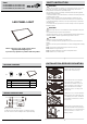
PACKAGE CONTENT
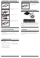
WIRING INSTRUCTIONS
LED fixture
A
B
C
pcs
PARTS
LED PANEL LIGHT
B
A
C
Wire Nuts P2
Wire Nuts P3
1
2
3
Wiring instructions as shown on the left.
.Use different socket to wire the AC line and 0-10V dimming controller.
.Secure the cover back to electrical wiring box after complete the wiring.
1. Lift up four mounting clips on the sides of
the fixture. Twist the hook 90 degree
towards outside as shown on Fig 1.
2. Insert luminaire into T-bar ceiling grid.
Secure safety cable(not included) to
connection hole as needed to meet local
seismic requirements. Safety cable and
method of attachment to the building
provided by contractor according to local
building codes.
3. Remove the cover of electrical wiring box.
Remove knockouts for AC input cables and
0-10V dimming control cables. Install listed
electrical fittings in the knockout sockets for
wire protection.
4. Plug in AC line (L,N and GND) to the LED
driver with 18-14 AWG wire by following the
wiring instructions. Use a separate knockout
socket(not included) to connect 0-10V
dimming controller.