
Manual


4. Technical Specifications
RuggedCom® RuggedSwitch® 33 RSG2288 Installation Guide Rev 108
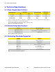
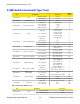
4.6.2.3. GBIC Gigabit Transceivers
Order
Code
Mode
Connector
Type
Cable
Type
(µm)
Tx λ (typ.)
(nm)
Tx min
(dBm)
Tx max
(dBm)
Rx
Sensitivity
(dBm)
Rx
Saturation
(dBm)
Distance
(typ.)
(km)
Power
Budget
(dB)
FG71 SM SC 9/125 1310 -9.5 -3 -21 -3 10 11.5
FG72 SM SC 9/125 1310 -7 -3 -24 -3 25 17
FG73 SM SC 9/125 1550 0 5 -23 -3 70 23
Table 4.8. GBIC Gigabit Transceivers
1. Maximum segment length is greatly dependent on factors such as fiber quality,
and number of patches and splices. Please consult RuggedCom sales associates
when determining maximum segment distances.
2. All optical power numbers are listed as dBm averages.
3. Distance ratings are typical but will depend on type of cabling, number of
connectors and splices.
4. FG54 and FG73 transceivers have an operating temperature range of -20°C to
+85°C. All other transceivers have an operating temperature range of -40°C to
+85°C.
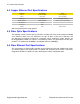
4.7. PTP Card Specifications
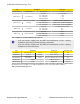
4.7.1. IRIG-B PWM Input
Parameter Typical Value
Input Voltage TTL-Compatible
Input Impedance
>200kΩ
Table 4.9. IRIG-B PWM Input Specifications
4.7.2. IRIG-B Output
Parameter Typical Value
Output Current (I
s
) 100 mA
Output Voltage (V
s
) 5 V
p-p
Output Impedance (R
s
)
50Ω
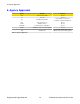
Table 4.10. IRIG-B003 PWM Output Specifications
Parameter Typical Value
Carrier Frequency 1 kHz
Modulation Depth
3:1±10%
Output Current (I
s
) 24 mA
Output Impedance (R
s
)
10Ω
Output Voltage (V
s
) 6 V
p-p
Table 4.11. IRIG-B123 AM Output Specifications