
Manual

3. Installation
RuggedCom® RuggedSwitch® 22 RSG2288 Installation Guide Rev 108
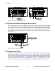
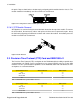
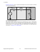
Figure 3.22. Console Port on Display Board
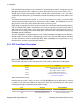
Figure 3.23. RS2000 Series Console Cable
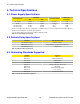
Signal Name (PC is DTE) DB9- Female RJ45 Male
DCD – Carrier detect 1 2
RxD – Receive data (to DTE) 2 5
TxD – Transmit data (from DTE) 3 6
DTR – Data terminal ready 4 3
GND - Signal ground 5 4
DSR – Data set ready 6 1*
RTS – Ready to send 7 8
CTS – Clear to send 8 7
RI – Ring Indicator 9 1*
Table 3.2. RS232 Over RJ45 Console Cable Pin-out
After initial configuration, the RSG2288 can be configured via a number of networked mechanisms
such as Telnet SSH, and the built-in secure web server. Consult the ROS™ User Guide for further
details.
• This port is not intended to be a permanent connection.
• Serial cable must not exceed 2m (6.5 ft) in length.
3.2.7. Ethernet Ports
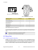
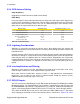
3.2.7.1. RJ45 Twisted-Pair Data Ports
RS2000 series Ethernet switches are equipped with up to nine 10/100/1000BaseTX ports
that allow connection to standard CAT-5 UTP cable with RJ45 male connectors. All RS2000
series RJ45 RuggedSwitch® products feature auto-negotiation, auto-polarity, and auto-crossover
functions. The RJ45 receptacles can also accept and take advantage of screened (commonly
known as “shielded”) cabling. The figure below shows the RJ45 port pins configuration.