
Manual

3. Installation
RuggedCom® RuggedSwitch® 17 RSG2288 Installation Guide Rev 108
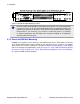
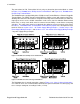
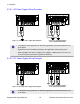
The connections for PS1, PS2 and the fail-safe relay are located on the terminal block as shown
in Figure 3.12, “RS2000 Series Phillips Screw Terminal Block” and Figure 3.13, “RS2000 Series
Phoenix Plug Terminal Block”.
The RSG2288 can be equipped with either a Phillips Screw Terminal Block or a Phoenix Pluggable
Terminal Block. The Phillips Screw Terminal Block has Phillips screws with compression plates,
allowing either bare wire connections or crimped terminal lugs. We recommend the use of #6 size
ring lugs to ensure secure, reliable connections under severe shock or vibration. Both terminal
blocks have a safety cover which must be removed via two Phillips screws before connecting
any wires. The safety cover must be re-attached after wiring to ensure personnel safety. Refer
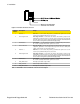
to Table 3.1, “RSG2288 Power Terminal Block Connection Description” for a description of each
terminal. Refer to Section 3.2.3.1, “AC Power Supply Wiring Examples ”, Section 3.2.3.2, “DC
Power Supply Wiring Examples ” and Section 3.2.3.3, “AC and DC Power Supply Wiring Example
” for power supply wiring examples.
Figure 3.12. RS2000 Series Phillips Screw Terminal Block
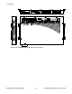
Figure 3.13. RS2000 Series Phoenix Plug Terminal Block
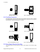
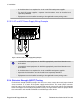
The RSG2288 chassis ground connection, shown in Figure 3.14, “Chassis Ground Connection”,
uses a #6-32 screw. It is recommended to terminate the ground connection in a #6 ring lug, and
to use a torque setting not exceeding 15 in•lbs (1.7 Nm).