RuggedSwitch® RSG2288 Hardware Installation Guide January 3, 2013 www.RuggedCom.
RuggedSwitch® RSG2288 RuggedSwitch® RSG2288 : Hardware Installation Guide Copyright © 2012 RuggedCom Inc. All Rights Reserved Dissemination or reproduction of this document, or evaluation and communication of its contents, is not authorized except where expressly permitted. Violations are liable for damages. All rights are reserved, particularly for the purposes of patent application or trademark registration. This document contains proprietary information, which is protected by copyright.
RuggedSwitch® RSG2288 Table of Contents FCC Statement And Cautions ................................................................................................... 6 1. Product Overview ................................................................................................................... 7 1.1. Functional Overview .................................................................................................... 7 1.2. Feature Highlights ....................................................
RuggedSwitch® RSG2288 List of Figures 1.1. RSG2288 LED Display Panel ........................................................................................... 2.1. RSG2288 Ethernet Port Layout ........................................................................................ 2.2. Ethernet Panel LEDs ........................................................................................................ 3.1. RSG2288 Rack Mount Chassis Orientation: Front Mount ........................................
RuggedSwitch® RSG2288 List of Tables 1.1. LED Display – Device status LED behavior definition ...................................................... 1.2. Port Status LED behavior definition .................................................................................. 3.1. RSG2288 Power Terminal Block Connection Description ................................................ 3.2. RS232 Over RJ45 Console Cable Pin-out ....................................................................... 3.3.
FCC Statement And Cautions FCC Statement And Cautions Federal Communications Commission Radio Frequency Interference Statement This equipment has been tested and found to comply with the limits for a Class A digital device pursuant to Part 15 of the FCC Rules. These limits are designed to provide reasonable protection against harmful interference when the equipment is operated in a commercial environment.
1. Product Overview 1. Product Overview 1.1. Functional Overview The RuggedSwitch® RSG2288 is a rugged, fully managed, modular Ethernet switch specifically designed to operate reliably in electrically harsh and climatically demanding utility substation, railway and industrial environments. The RSG2288 includes the IEEE 1588 v2 protocol with hardware time stamping, allowing high precision time synchronization over the Ethernet network with accuracies of 1µs or better.
1. Product Overview Cyber Security Features • Multi-level user passwords • SSH/SSL encryption • MAC-based port security • Selective port enable/disable • Port-based network access control using IEEE 802.1x • VLAN support (IEEE 802.
1. Product Overview Rugged Operating System (ROS™) Networking Features • Simple plug and play operation – automatic learning, negotiation, and crossover detection • RSTP (Rapid Spanning Tree Protocol) support: IEEE 802.1w • eRSTP™ (Enhanced Rapid Spanning Tree) support, < 5ms network fault recovery • QoS (Quality of Service) support: IEEE 802.1p, for real-time traffic • Port rate limiting and broadcast storm limiting • VLAN (Virtual LAN) support: IEEE 802.
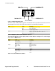
1. Product Overview Figure 1.1. RSG2288 LED Display Panel The device status LEDs provide a quick visual indication of the operational status of the unit. The following table lists the possible LED colors and their corresponding descriptions.
2. RuggedSwitch® Modules 2. RuggedSwitch® Modules 2.1. Ethernet Panel Description The Ethernet connector panel of the RSG2288 is organized into six slots, five of which are modular and may be selected at the time the unit is ordered. The figure below shows the physical layout of these ports. Figure 2.1. RSG2288 Ethernet Port Layout Slots 1, 2, 3 and 4 support two-port Ethernet modules up to 1Gbps. Slot 5 supports a one-port module up to 1Gbps. Slot 6 contains the PTP Source Card (see Section 3.
3. Installation 3. Installation 3.1. Mounting RSG2000 series products are designed for maximum mounting and display flexibility. Customers can order an RSG2000 series switch that can be mounted in a standard 19" rack, 1" DIN Rail, or directly onto a panel. 3.1.1. Rack Mounting For rack mount installations, the RSG2000 series can be ordered with connectors on the front panel or on the rear of the chassis.
3. Installation Figure 3.3. Rack Mount Adapter Mounting Locations Since heat within the RSG2288 is channeled to the enclosure, it is recommended that 1 rack-unit of space (1.75") be kept unpopulated and free of equipment above each RS2000 series product to allow for a small amount of convectional airflow.
3. Installation Figure 3.4.
3. Installation Figure 3.5. Panel / DIN Rail Mounting Diagram (Connectors at Bottom) 3.2. Fiber Optic Transceiver Orientation and Connection Depending on the order code of the product, the RS2000 series products can be equipped with several different types of fiber optic ports. The Transmit (TX) and Receive (RX) connections of each port must be properly connected and matched for proper link and operation.
3. Installation Figure 3.6. 1000LX SFP (miniGBIC) Module and LC connector Figure 3.7. 1000LX GBIC connector 3.2.2. Fixed Fiber Transceivers The following figures show front and top views of the fixed fiber transceiver modules supported by RuggedSwitch®. Note that when the module daughter card is installed in the unit, most of the connector body as shown in the illustrations is not visible. Figure 3.8. 1000LX LC connector Figure 3.9. 1000LX SC connector Figure 3.10. 100FX/1000LX ST connector Figure 3.
3. Installation The connections for PS1, PS2 and the fail-safe relay are located on the terminal block as shown in Figure 3.12, “RS2000 Series Phillips Screw Terminal Block” and Figure 3.13, “RS2000 Series Phoenix Plug Terminal Block”. The RSG2288 can be equipped with either a Phillips Screw Terminal Block or a Phoenix Pluggable Terminal Block. The Phillips Screw Terminal Block has Phillips screws with compression plates, allowing either bare wire connections or crimped terminal lugs.
3. Installation Figure 3.14. Chassis Ground Connection Terminal Number Description Usage 1 PS1 Live / + PS1 Live / + is connected to the positive (+) terminal if the power source is DC or to the (Live) terminal if the power source is AC. 2 PS1 Surge Ground PS1 Surge Ground is connected to the Chassis Ground via a jumper on the terminal block. Surge Ground is used as the ground conductor for all surge and transient suppression circuitry.
3. Installation 3.2.3.1. AC Power Supply Wiring Examples Figure 3.15. AC Single Power Supply Wiring Example Figure 3.16. AC Dual Redundant Power Supply Wiring Example • 100-240VAC rated equipment: A 250VAC appropriately rated circuit breaker must be installed. • Equipment must be installed according to the applicable country wiring codes. • When equipped with two HI voltage power supplies, independent AC sources can be used to power the product for greater redundancy. 3.2.3.2.
3. Installation • A circuit breaker is not required for 12-24 or 48 VDC rated power supplies. • For dual DC power supplies, separate circuit breakers must be installed and separately identified. • Equipment must be installed according to the applicable country wiring codes. 3.2.3.3. AC and DC Power Supply Wiring Example + Figure 3.19. DC and AC Power Supply Wiring Example • 125/250VDC rated equipment: A 300VDC appropriately rated circuit breaker must be installed.
3. Installation Figure 3.20. Dielectric Strength (HIPOT) Testing 3.2.5. Failsafe Alarm Relay Wiring and Specifications The “Failsafe” output relay is provided to signal critical error conditions that may occur on RS2000 series products. The contacts are energized upon power-up of the unit and remain energized unless a critical error occurs. The proper relay connections are shown in the figure below. Control of this output is user selectable and can be programmed via the Rugged Operating System (ROS).
3. Installation Figure 3.22. Console Port on Display Board Figure 3.23. RS2000 Series Console Cable Signal Name (PC is DTE) DB9- Female RJ45 Male DCD – Carrier detect 1 2 RxD – Receive data (to DTE) 2 5 TxD – Transmit data (from DTE) 3 6 DTR – Data terminal ready 4 3 GND - Signal ground 5 4 DSR – Data set ready 6 1* RTS – Ready to send 7 8 CTS – Clear to send 8 7 RI – Ring Indicator 9 1* Table 3.2.
3. Installation Figure 3.24. RJ45 Port Pin Configuration Pin Description 1 RX + 2 RX - 3 TX + 6 TX - 4, 5, 7, 9 No Connection Table 3.3. RJ45 Ethernet Pin Assignment 3.2.7.2. Gigabit Ethernet 1000Base-TX Cabling Recommendations The IEEE 802.3ab Gigabit Ethernet standard defines 1000 Mbit/s Ethernet communications over distances of up to 100 meters using all 4 pairs in category 5 (or higher) balanced unshielded twisted-pair cabling.
3. Installation 3.2.8. Pluggable optics – Installation, removal, and precautions The RS2000 series of products can be ordered with two pluggable optical form factors: SFP (Small Form-factor Pluggable), and GBIC (GigaBit Interface Converter). SFP and GBIC modules can be safely inserted and removed while the chassis is powered and operating – a feature also referred to as “hot-swappable”. Nevertheless, when inserting or removing optics there are several precautions that should be taken.
3. Installation the optics. Depress both latches simultaneously and gently pull the module from the chassis. The module should be immediately stored in an ESD-safe environment. Figure 3.27. Locking Latch Location on GBIC Optical Modules 3.2.8.3. SFP Module Removal SFP Modules are removed using the metal bail latch located on the top of the module. To remove the SFP module, disconnect any cables and replace the dust cover to protect the optics.
3. Installation NTP (Network Time Protocol) is the standard for synchronizing the clocks of computer systems throughout the Internet and is suitable for systems that require accuracies in the order of 1 ms. IRIG-B (Inter Range Instrumentation Group, mod B) time synchronization is an even older, established, inter-device time synchronization mechanism providing accuracy on the order of 1ms to 1µs.
3. Installation Color GPS Input IRIG-B PWM Input no longer sees the minimum number of required satellites.) Off No signal detected No signal detected Table 3.8. PTP Card LED Functions 3.3.2. GPS Antenna Installation The signals received from the GPS satellite network are at a frequency of 1575.42 MHz with a minimum power of -162 dBW. The GPS antenna must have a clear view of the sky in order to receive the low power signals and track the maximum number of satellites.
3. Installation 3.3.4. GPS Antenna Cabling Cable Impedance RuggedCom recommends low loss 50Ω coaxial cabling. Cable Delay Using any length of coaxial cable will add some time delay to the GPS signal, which degrades the accuracy of the calculated time and position. The time delay is dependent on the type of dielectric material in the cable and ranges from 1 to 2 ns/ft. The table below gives some examples of the delay that can be expected based on the dielectric type.
3. Installation B Simplified Schematic” shows a simplified circuit diagram of the interface between an IRIG-B source and connected devices. Figure 3.30.
4. Technical Specifications 4. Technical Specifications 4.1. Power Supply Specifications Input Range Power Supply Type 12 – 24 VDC 48 VDC c HI (125/250 VDC) c HI (110/230 VAC) Min Max 10 VDC 36 VDC Internal Fuse Rating b 6.3A(F) 36 VDC 59 VDC 3.15A(T) 88 VAC 300 VDC 2A(T) 85 VAC 264 VAC Max. Power a Consumption b 28 W 28 W bc 28 W bc 28 W 2A(T) a Power consumption varies based on configuration. 10/100Base-TX ports consume roughly 1W less than fiber optic ports.
4. Technical Specifications 4.4. Copper Ethernet Port Specifications Parameter Specification Notes Speed 10/100/1000 Mbps Auto-negotiating; Duplex FDX / HDX Auto-negotiating Cable-Type > Category 5 Shielded/Unshielded Wiring Standard TIA/EIA T568A/B Auto-Crossover, Auto-Polarity Max Distance 100 m Connector RJ45 Isolation 1.5kV RMS 1-minute Table 4.4. Copper Ethernet Port Specifications 4.5.
4. Technical Specifications 4.6.1. Fast Ethernet (10/100Mbps) Optical Specifications Order Code Mode Connector Type FXA01 MM ST FXA02 MM SC FXA11 MM LC Cable Type (µm) Tx λ (typ.) (nm) 62.5/125 Tx min. (dBm) -19 1308 50/125 62.5/125 -22.5 -19 1308 50/125 62.5/125 -22.5 1310 62.5/125 -19 -19 1308 Rx Rx Distance Tx max. Sensitivity Saturation (typ.) (dBm) (dBm) (dBm) (km) -14 -31 -14 2 -14 -31 -14 2 -14 -32 -14 2 -14 -31 -14 2 Power Budget (dB) 12 8.5 12 8.
4. Technical Specifications 4.6.2.3. GBIC Gigabit Transceivers Order Code Mode Connector Type Cable Type (µm) Tx λ (typ.) (nm) Tx min (dBm) Tx max (dBm) Rx Rx Distance Sensitivity Saturation (typ.) (dBm) (dBm) (km) Power Budget (dB) FG71 SM SC 9/125 1310 -9.5 -3 -21 -3 10 11.5 FG72 SM SC 9/125 1310 -7 -3 -24 -3 25 17 FG73 SM SC 9/125 1550 0 5 -23 -3 70 23 Table 4.8. GBIC Gigabit Transceivers 1.
4. Technical Specifications 4.8. Operating Environment Parameter Range Comments Ambient Operating Temperature -40 to 85°C Ambient Temperature as measured from a 30cm radius surrounding the center of the enclosure. Ambient Relative Humidity 5% to 95% Non-condensing Ambient Storage Temperature -40 to 85°C Table 4.12.
4. Technical Specifications 4.9. Mechanical Specifications Parameter Value Comments Dimensions 18.29 × 12.14 × 1.75 in (464.57 × 308.36 × 44.45 mm) (Length × Width × Height) with mounting brackets installed Weight 10 lb (4.5 kg) Enclosure 18AWG galvanized steel Table 4.13. Mechanical Specifications Figure 4.1.
5. EMI And Environmental Type Tests 5. EMI And Environmental Type Tests Test IEC 61000-4-2 ESD IEC 61000-4-3 Radiated RFI IEC 61000-4-4 Burst (Fast Transient) IEC 61000-4-5 IEC 61000-4-6 IEC 61000-4-8 IEC 61000-4-29 IEC 61000-4-11 IEC 61000-4-12 Surge Induced (Conducted) RFI Magnetic Field Voltage Dips & Interrupts Damped Oscillatory Mains Frequency Voltage IEC 61000-4-17 Ripple on D.C.
5. EMI And Environmental Type Tests Test IEEE C37.90.2 IEEE C37.90.1 IEEE C37.90.1 IEEE C37.90 IEEE C37.90 Description Radiated RFI Fast Transient Oscillatory H.V. Impulse Dielectric Strength Test Levels Enclosure ports 35 V/m Signal ports +/- 4kV @ 2.5kHz D.C. Power ports +/- 4kV A.C. Power ports +/- 4kV Earth ground ports +/- 4kV Signal ports 2.5kV common mode @1MHz D.C. Power ports 2.5kV common, 1kV diff. mode@1MHz A.C. Power ports 2.5kV common, 1kV diff.
6. Agency Approvals 6. Agency Approvals Agency Standards Comments CSA CSA C22.2 No. 60950 Passed UL UL 60950 Passed CE EN 60950, EN 61000-6-2 CE Compliance is claimed via Declaration of Self Conformity Route FCC FCC Part 15, Class A Passed CISPR EN55022, Class A Passed FDA/CDRH 21 CFR Chapter 1, Subchapter J Passed IEC/EN EN60825-1:1994 + A11:1996 + A2:2001 Passed ISO ISO9001:2000 Designed and manufactured using a ISO9001: 2000 certified quality program Table 6.1.
7. Warranty 7. Warranty RuggedCom warrants this product for a period of five (5) years from the date of purchase. This product contains no user-serviceable parts. Attempted service by unauthorized personnel shall render all warranties null and void. For warranty details, visit www.RuggedCom.com or contact your customer service representative. Should this product require service, contact the factory at: RuggedCom Inc.