RuggedSwitch™ RS900G Hardware Installation Guide Revision 107 - April 10, 2013 www.RuggedCom.
RuggedSwitch™ RS900G RuggedSwitch™ RS900G: Hardware Installation Guide Copyright © 2013 RuggedCom Inc. All Rights Reserved Dissemination or reproduction of this document, or evaluation and communication of its contents, is not authorized except where expressly permitted. Violations are liable for damages. All rights are reserved, particularly for the purposes of patent application or trademark registration. This document contains proprietary information, which is protected by copyright.
RuggedSwitch™ RS900G Table of Contents FCC Statement And Cautions ................................................................................................... 6 1. Product Overview ................................................................................................................... 7 1.1. RS900G Front Panel ................................................................................................... 9 1.2. RS900G Bottom Panel ......................................................
RuggedSwitch™ RS900G List of Figures 1.1. 1.2. 2.1. 2.2. 2.3. 2.4. 2.5. 2.6. 2.7. 3.1. RS900G Front Panel .......................................................................................................... 9 RS900G Bottom Panel ....................................................................................................... 9 DIN Rail Mounting ............................................................................................................ 10 Power Supply Inputs ...................
RuggedSwitch™ RS900G List of Tables 1.1. RS900G Front Panel LED Definitions ................................................................................ 9 2.1. RS232 Female DCE Pinout .............................................................................................. 14 2.2. RJ45 Ethernet Pin Assignment ......................................................................................... 15 3.1. Operating Environment .......................................................................
FCC Statement And Cautions FCC Statement And Cautions Federal Communications Commission Radio Frequency Interference Statement This equipment has been tested and found to comply with the limits for a Class A digital device pursuant to Part 15 of the FCC Rules. These limits are designed to provide reasonable protection against harmful interference when the equipment is operated in a commercial environment.
1. Product Overview 1. Product Overview The RuggedSwitch™ RS900G is an industrially hardened, fully managed Ethernet switch providing dual fiber optical Gigabit Ethernet ports and eight Fast Ethernet copper ports. Designed to operate reliably in harsh industrial environments, the RS900G provides a high level of immunity to electromagnetic interference and heavy electrical surges typical of environments found in electric utility substations, factory floors or in curb side traffic control cabinets.
1. Product Overview Simple Plug and Play Operation • Automatic learning of up to 8192 MAC addresses • Auto-negotiation on all 10/100BaseTX ports • Auto-MDI/MDIX (crossover) on all 10/100BaseTX ports • LED indicators for link, activity and speed ROS™ Advanced Network Management • Enhanced Rapid Spanning Tree (eRSTPTM) • Quality of Service (802.1p) for real-time traffic • Port rate limiting: 128kbps to 8Mbps • VLAN (802.
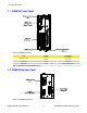
1. Product Overview 1.1. RS900G Front Panel Figure 1.1. RS900G Front Panel LED LINK LED (Yellow) Activity Description Solid Link Established Blinking Tx/Rx Activity Power LED Solid Power On Alarm LED Solid Alarm condition exists Table 1.1. RS900G Front Panel LED Definitions 1.2. RS900G Bottom Panel Figure 1.2.
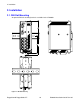
2. Installation 2. Installation 2.1. DIN Rail Mounting An optional DIN rail mounting bracket is available for the RS900G. Figure 2.1.
2. Installation 2.2. Power Supply Wiring and Grounding 2.2.1. HI Power Supply Wiring and Grounding Figure 2.2. Power Supply Inputs The RS900G HI power supply inputs are connected as follows: 1. +/L should be connected to AC (Hot) 2. -/N should be connected to AC (Neutral) 3. Surge Ground is connected to the Chassis Ground via a braided cable or other appropriate grounding wire. Surge Ground is used as the ground conductor for all surge and transient suppression circuitry internal to the RS900G unit. 4.
2. Installation 2.2.2. DC Power Supply Wiring and Grounding Figure 2.3. DC Power Supply Wiring and Grounding The RS900G low voltage DC power supply features reverse polarity protection and dual independent inputs. This feature allows the connection of two DC sources with the same nominal voltage to provide redundant power supply inputs. The DC source must be connected to the DC inputs according to the polarity markings on the unit. 1.
2. Installation 2.3. HIPOT (Dielectric Strength) Testing Units which are to be “HIPOT” tested in the field must have the braided ground cable disconnected (see Figure 2.4, “HIPOT (Dielectric Strength) Testing”) during the HIPOT test. This is required in order to prevent the transient/surge suppression circuitry, which is connected to Surge Ground, from being activated during the HIPOT test. Figure 2.4. HIPOT (Dielectric Strength) Testing 2.4.
2. Installation Figure 2.6. RS232 Female Connector Pin Signal 1 No Connection 2 Transmit Data 3 Receive Data 4 No Connection 5 Ground 6 No Connection 7 No Connection 8 No Connection 9 No Connection Table 2.1. RS232 Female DCE Pinout This port is not intended to be a permanent connection and the cable shall be less than 2m (6.5 ft) in length.
2. Installation 2.6. RJ45 Ports: Signal Description The RS900G has several 10/100BaseTX ports that allow connection to standard CAT-5 UTP cable with RJ45 male connectors. The RJ45 receptacles are directly connected to the chassis ground on the unit and can accept shielded CAT-5 cables. If shielded cables are used, care must be taken to ensure the shielded cables do not form a ground loop via the shield wire and the RJ45 receptacles at either end. Figure 2.7.
3. Specifications 3. Specifications 3.1. Operating Environment Parameter Range Comments Ambient Operating Temperature -40 to 85°C Ambient Temperature as measured from a 30cm radius surrounding the center of the RS900G enclosure. Ambient Relative Humidity 5% to 95% Non-condensing Ambient Storage Temperature -40 to 85°C Operating Altitude 0 to 15240m (0 to 50000 ft) Over temperature range of -40 to 85°C Table 3.1. Operating Environment 3.2.
3. Specifications 3.5. Fiber Optic Port Specifications For maximum flexibility, RuggedCom Inc. offers a number of different transceiver choices for Gigabit fiber optic communications. The following table details fiber optic specifications based on the order code/transceiver selected at time of ordering. Mode / Connector Tx λ (nm) Cable a Type 1. 2LCMM MM / LC 850 50µ/125 -9.5 / -4 -20 0 0.5 2LC10 SM / LC 1310 9µ/125 -9.
3. Specifications 3.6. Physical Dimensions Figure 3.1. RS900G Physical Dimensions Parameter Value Comments Dimensions 7.4 × 2.6 × 5.0 inches (187.96 × 66.04 × 127.0 mm) (Length × Width × Depth Weight 2.7 lbs (1.2 kg) Enclosure 20 AWG Galvanized Steel Table 3.6.
3. Specifications 3.7. Type Test Specifications 3.7.1. IEC 61850-3 Type Tests Test IEC 61000-4-2 ESD IEC 61000-4-3 Radiated RFI IEC 61000-4-4 IEC 61000-4-5 IEC 61000-4-6 IEC 61000-4-8 IEC 61000-4-29 IEC 61000-4-11 IEC 61000-4-12 Burst (Fast Transient) Surge Induced (Conducted) RFI Magnetic Field Voltage Dips & Interrupts Damped Oscillatory Mains Frequency Voltage IEC 61000-4-17 Ripple on D.C.
3. Specifications 3.7.2. IEEE 1613 Type Tests IEEE Test IEEE 1613 Clause C37.90.3 9 ESD C37.90.2 8 Radiated RFI C37.90.1 Description 7 C37.90.1 Fast Transient 7 C37.90 Oscillatory 6 C37.90 H.V. Impulse 6 Test Levels Enclosure Contact +/- 8kV Enclosure Air +/- 15kV Enclosure ports 35 V/m Signal ports +/- 4kV @ 2.5kHz D.C. Power ports +/- 4kV A.C. Power ports +/- 4kV Earth ground ports +/- 4kV Signal ports 2.5kV common mode @ 1MHz D.C. Power ports 2.
3.
3. Specifications 3.8. Agency Approvals Agency Standards Comments CSA CSA C22.2 No. 60950, UL 60950 Approved CE EN 60950, EN 61000-6-2 CE Compliance is claimed via Declaration of Self Conformity Route FCC FCC Part 15, Class A Approved CISPR EN55022, Class A Approved FDA/CDRH 21 CFR Chapter 1, Subchapter J Approved IEC/EN EN60825-1:1994 + A11:1996 + A2:2001 Approved CSA Hazardous Locations Class 1, Division 2, Groups A, B, C,& D.
Appendix A. Warranty Appendix A. Warranty RuggedCom warrants this product for a period of five (5) years from the date of purchase. This product contains no user-serviceable parts. Attempted service by unauthorized personnel shall render all warranties null and void. For warranty details, visit www.RuggedCom.com or contact your customer service representative. Should this product require service, contact the factory at: RuggedCom Inc.