RuggedWireless RuggedWireless Wireless RS900W 900W Family Installation Guide www.ruggedcom.com RuggedCom Inc.
Federal Communications Commission Radio Frequency Interference Statement This equipment has been tested and found to comply with the limits for a Class A digital device pursuant to Part 15 of the FCC Rules. These limits are designed to provide reasonable protection against harmful interference when the equipment is operated in a commercial environment.
Table of Contents 1 2 3 4 5 Product Overview.................................................................................................................. 4 1.1 Functional Overview ....................................................................................................... 4 1.2 Feature Highlights........................................................................................................... 4 1.3 RS900W Family Front Panel View...................................................
1 Product Overview 1.1 Functional Overview The RuggedWireless RS900W family of products are industrially hardened, fully managed, IEEE 802.11g Access Points with integrated Ethernet switching, specifically designed to operate reliably in electrically harsh and climatically demanding industrial environments.
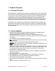
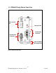
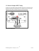
1.3 RS900W Family Front Panel View Power and Alarm LEDs Reset LED Port 9: Antenna #1 Ports 7 – 8: 10/100 BaseTx or 100 BaseFx Ports 1 – 6: 10/100 BaseTx Port 9: Antenna #2 Fail-Safe Relay Power Port Figure 1 - Front Panel Description ITEM LINK LED (Yellow) Power LED Alarm LED Activity Solid Blinking – Once per second Solid Solid Comments Link Established Tx/Rx Activity Power On Alarm condition exists Table 1 - Status LEDs 5 2008 RuggedCom Inc.
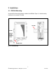
1.4 RS900W Family Bottom Panel View RS232 Console Port Chassis ground Power Supply Connection Fail-Safe Relay Connection Optional DIN Rail Mounting Bracket Figure 2 - Bottom Panel Description 6 2008 RuggedCom Inc.
2 Installation 2.1 DIN Rail Mounting An optional DIN rail mounting bracket is available for the RS900W. Figure 2.1.1 details mounting instructions for the standard 1” DIN Rail. Din Rail Din Rail Optional Din Rail mounting bracket Release direction Release latch Figure 3 - DIN Rail Mounting 7 2008 RuggedCom Inc.
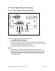
2.2 Power Supply Wiring and Grounding 2.2.1 AC Power Supply Wiring and Grounding Figure 4 - Power Supply Inputs The AC power supply inputs should be connected as follows: 1. +/L should be connected to AC Line/Hot. 2. -/N should be connected to AC Neutral. 3. Surge Ground should be connected to the Chassis Ground via a braided cable or other appropriate grounding wire. Surge Ground is used as the ground conductor for all surge and transient suppression circuitry internal to the unit. 4.
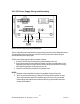
2.2.2 DC Power Supply Wiring and Grounding Figure 5 - DC Power supply wiring and grounding diagram The low voltage DC power supply features reverse polarity protection and dual independent inputs. The latter feature allows the connection of two DC sources with the same nominal voltage to provide redundant power supply inputs. The DC power supply inputs should be connected as follows: 1. Connect to the DC inputs according to the polarity markings on the unit. 2.
2.3 Dielectric Strength (HIPOT) Testing Units which are to have dielectric strength testing (HIPOT testing) done in the field must have the braided ground cable disconnected during the test. This is required in order to prevent the surge suppression circuitry, which is connected to surge ground, from being activated. Figure 6 - Dielectric Strength Testing 10 2008 RuggedCom Inc.
2.4 Failsafe Output Wiring and Specifications The Failsafe output relay is provided to signal critical error conditions that may occur on the unit. The contacts are energized upon power up of the unit and remain energized until an alarm condition or power loss occurs. Figure 7 - Failsafe Output Relay 11 2008 RuggedCom Inc.
2.5 RS232 Port Wiring The RS232 port is used for configuring the unit. A straight-through serial cable with a DB-9 connector is required. There is no need to crossover the Transmit and Receive signals from the PC side since this has been done internally as is shown below.
2.6 RJ45 Ports – Signal Description Units with 10/100Base-TX ports allow connection to standard Category 5 (CAT-5) unshielded twisted-pair (UTP) cable with RJ45 male connectors. The RJ45 receptacles are directly connected to the chassis ground on the unit and can accept CAT-5 shielded twisted-pair (STP) cables. If shielded cables are used, care must be taken to ensure the shielded cables do not form a ground loop via the shield wire and the RJ45 receptacles at either end.
3 Technical Specifications 3.1 Operating Environment Parameter Range Ambient Operating Temperature -40 to 85°C Ambient Storage Temperature Ambient Relative Humidity -40 to 85°C 5% to 95% Comments Ambient Temperature as measured from a 30 cm radius surrounding the center of the enclosure. Non-condensing Table 4 - Operating Environment 3.
Isolation Comments 1500 Vrms Dielectric test voltage (1 minute) between coil & contacts Table 7 - Failsafe Relay Isolation 3.4 RJ45 Ethernet Port Specifications Data Port Media Distance Connector Type 10/100 Mbps CAT-5 UTP or STP 100m RJ45 Table 8 – RJ45 Ethernet Port Specifications 15 2008 RuggedCom Inc.
3.5 Wireless Standards Supported Standard Parameter Mode Notes IEEE 802.11g 54 Mbps (WLAN) Full Access Point 2.4 Ghz ISM IEEE 802.11b 11 Mbps (WLAN) Client support IEEE 802.11i Strong Encryption WPA2-AES (CCMP) Enhanced Encryption WPA-TKIP (RC4) Backwards compatibility Robust Secure Network (RSN) Temporal keys Basic Encryption WEP (RC4) Up to 4 static keys Wireless Authentication ‘Personal’ or ‘Enterprise’ PSK or RADIUS IEEE 802.1x Table 9 - Wireless Standards supported 3.
3.7 IEEE 802.11b/g The channel identifiers, channel center frequencies, and regulatory domains of each IEEE 802.11b/g 22-MHz-wide channel are shown in Figure 2.7.
3.8 Fiber Optical Port Specifications Order Code Speed Standard Mode / Connector Tx (nm) Cable Type (um) Tx min (dBm) Tx max (dBm) Rx Sensitivity (dBm) Rx Saturation (dBm) Typical Distance (km) Power Budget (dB) MJ 100FX MM/MTRJ 1300 50/125 62.5/125 -22.5 -19 -14 -14 -33.5 -33.5 -14 -14 2 2 11 14.5 MC 100FX MM/SC 1300 50/125 62.5/125 -22.5 -19 -14 -14 -33.9 -33.9 -14 -14 2 2 11.4 14.9 MT 100FX MM/ST 1300 50/125 62.5/125 -22.5 -19 -14 -14 -33.9 -33.9 -14 -14 2 2 11.
3.9 Physical Dimensions Figure 10 - Mechanical Specifications 19 2008 RuggedCom Inc.
Parameter Dimensions Value 7,4 x 2,6 x 5,0 inches (187,96) x (66,04) x (127,0) mm 2.7 lb (1.2 Kg) 20 AWG Galvanized Steel Weight Enclosure Comments (Length x Width x Depth) Table 13 - Physical Dimensions 3.10 Agency Approvals Agency CSA Standards CSA C22.2 No.
5 Appendix A - RuggedWireless ™ Frequently Asked Questions (FAQ) What factors can affect wireless coverage/range? Range estimates are typical and require line of sight. Basically that means you will need a clear unobstructed view of the antenna from the remote point in the link. Keep in mind that walls and obstacles will limit your operating range and could even prevent you from establishing a link. Signals in the 2.4 Ghz generally will not penetrate metal or concrete walls.
dBm 0 1 2 3 4 5 6 7 8 9 10 11 12 13 14 15 Watts 1.0 mW 1.3 mW 1.6 mW 2.0 mW 2.5 mW 3.2 mW 4 mW 5 mW 6 mW 8 mW 10 mW 13 mW 16 mW 20 mW 25 mW 32 mW dBm 16 17 18 19 20 21 22 23 24 25 26 27 28 29 30 31 Watts 40 mW 50 mW 63 mW 79 mW 100 mW 126 mW 158 mW 200 mW 250 mW 316 mW 398 mW 500 mW 630 mW 800 mW 1.0 W 1.3 W dBm Watts 32 1.6 W 33 2.0 W 34 2.5 W 35 3.2 W 36 4.0 W 37 5.0 W 38 6.3 W 39 8.