RuggedVDSL RuggedVDSL VDSL RS91 RS910L Serial and Ethernet Device Server with Ethernet over VDSL Uplink Installation Guide www.ruggedcom.com RuggedCom Inc.
Federal Communications Commission Radio Frequency Interference Statement This equipment has been tested and found to comply with the limits for a Class A digital device pursuant to Part 15 of the FCC Rules. These limits are designed to provide reasonable protection against harmful interference when the equipment is operated in a commercial environment.
Table of Contents 1 2 3 4 5 6 7 Product Overview ............................................................................................................................... 5 1.1 Functional Overview ................................................................................................................... 5 1.2 Feature Highlights ...................................................................................................................... 5 1.3 RS910L Front Panel Description .
Table of Figures Figure 1 - RS910L Front Panel Description............................................................................................... 6 Figure 2 - RS910L Bottom Panel Description ............................................................................................ 7 Figure 3 - RS910L DIN Rail Mounting....................................................................................................... 8 Figure 4 - RS910L Power Supply Inputs .......................................
1 Product Overview 1.1 Functional Overview The RuggedVDSLTM RS910L is an industrial hardened serial server and managed Ethernet switch supporting Ethernet over VDSL (EoVDSL). The RS910L can be configured with 2 serial ports (RS485/RS422/RS232/fiber) and/or 2 Ethernet ports (copper or fiber). The RS910L can interconnect multiple types of intelligent electronic devices (IEDs) that have different methods of communications.
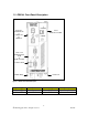
1.3 RS910L Front Panel Description Ports 3 & 4 10/100Base-TX or 100Base-FX Or 10Base-FL Port 9 Ethernet over VDSL Ports 1 & 2 RS485/422/232 Serial Or Serial over Fiber Power & Alarm Failsafe Relay Power Port Figure 1 - RS910L Front Panel Description Status LED Power LED Alarm LED Colour Green Red Activity Solid Solid Comments Power On Alarm condition exists Table 1 - Status LEDs 6 2007 RuggedCom Inc.
1.4 RS910L Bottom Panel Description Console Port Chassis Ground Power Port Failsafe Relay Optional Din-Rail Mounting Bracket Figure 2 - RS910L Bottom Panel Description 7 2007 RuggedCom Inc.
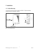
2 Installation 2.1 Din Rail Mounting An optional DIN rail mounting bracket is available for the RS910L. The figure below details mounting instructions for the standard 1” DIN Rail. Figure 3 - RS910L DIN Rail Mounting 8 2007 RuggedCom Inc.
2.2 Power Supply Wiring and Grounding 2.2.1 AC Power Supply Wiring and Grounding Figure 4 - RS910L Power Supply Inputs The RS910L AC power supply inputs should be connected as follows: 1. +/L should be connected to AC Line/Hot. 2. -/N should be connected to AC Neutral. 3. Surge Ground should be connected to the Chassis Ground via a braided cable or other appropriate grounding wire. Surge Ground is used as the ground conductor for all surge and transient suppression circuitry internal to the unit. 4.
2.2.2 DC Power Supply Wiring and Grounding Figure 5 - DC Power supply wiring and grounding diagram The RS910L low voltage DC power supply features reverse polarity protection and dual independent inputs. The latter feature allows the connection of two DC sources with the same nominal voltage to provide redundant power supply inputs. The RS910L DC power supply inputs should be connected as follows: 1. Connect to the DC inputs according to the polarity markings on the unit. 2.
2.2.3 Dielectric Strength Testing Units which are to have dielectric strength testing (HIPOT testing) done in the field must have the braided ground cable disconnected during the test. This is required in order to prevent the surge suppression circuitry, which is connected to surge ground, from being activated. Figure 6 - Dielectric Strength Testing 11 2007 RuggedCom Inc.
2.3 Failsafe Output Wiring The Failsafe output relay is provided to signal critical error conditions that may occur on the RS910L. The contacts are energized upon power up of the unit and remain energized until an alarm condition or power loss occurs. The behavior of the failsafe relay is configurable via the RuggedSwitch Operating System. Consult the RuggedSwitch Users Guide for details. Figure 7 - RS910L Failsafe Output Relay 12 2007 RuggedCom Inc.
2.4 RS232 Console Port Wiring The RS232 port is used for configuring the RS910L. A straight-through serial cable with a DB-9 connector is required. There is no need to crossover the TxD and RxD signals from the PC side since this has been done internally as is shown in the figure below.
3 Serial Ports The RS910L can be equipped with a Fiber Serial Interface, RS232/RS485/RS422 DB9 serial ports or RS232/RS485/RS422 RJ45 serial ports. 3.1.1 Fiber Serial Interface The RS910L can be equipped with a Fiber Serial Interface (ST connector only) which allows RS485, RS422, or RS232 devices to communicate over secure, noise immune, optically isolated, fiber optic cabling at extended distances as well as protocol independent conversion to multimode fiber optics.
Pin 1 2 3 4 5 6 7 8 9 Shield RS232 Mode RS485 Mode RS422 Mode CD TX TX/RX+ (A) TX+ RX RX+ DTR Common (Isolated Ground) DSR RXCTS TX/RX - (B) TXRTS RI (NC) Chassis Ground Figure 10: DB9 Port pin-out NOTE: Pins 1, 4, and 6 are connected internally. Pins 7 and 8 are connected internally. No internal termination is provided. 3.1.3 RS232/RS485/RS422 via RJ45 Each port is individually selectable via software to be RS232, RS485 or RS422. The RJ45 port and pin-out is shown in Figure 11.
Pin 1 2 3 4 5 6 7 8 Shield RS232 Mode RS485 Mode RS422 Mode DSR RXDCD DTR Common (Isolated Ground) RX RX+ TX TX/RX + (A) TX + CTS RTS TX/RX - (B) TX Chassis Ground Figure 11: RJ45 Port pin-out NOTE: Pins 1, 2, and 3 are connected internally. Pins 7 and 8 are connected internally. No internal termination is provided. 3.1.
Figure 12: Conceptual recommended RS485 wiring diagram 3.1.5 Serial Port Transient Protection RuggedCom does not recommend the use of copper cabling of any length for critical real-time substation automation applications. However, transient suppression circuitry is present on all copper ports to protect against damage from electrical transients and to ensure IEC 61850-3 and IEEE 1613 Class 1 conformance.
4 Ethernet Ports 4.1 RJ11 Ethernet over VDSL Port 4.1.1 Overview The Ethernet over VDSL (EoVDSL) port on RS910L operates in pairs with one configured as the Master and the other as the Slave. In VDSL literature the terms Central Office (CO) or Line Termination (LT) are used interchangeably for the Master and the terms Customer Premise Equipment (CPE) or Network Termination (NT) are used interchangeably for the Slave. Configuration of Master or Slave mode is done through the RuggedSwitch Operating System.
4.1.2 Wiring VDSL typically operates over 2-wire CAT-3 wiring; however, other categorized or uncategorized twisted-pair wiring will work although the performance will vary depending on the distance and cable characteristics. It is important that the wiring used does not have any open leads (also known as bridged taps or drop-lines) along its length because this will impact performance by degrading the signal. 4.1.3 Configuration & Setup 1. Log into the RuggedSwitch Operating System. 2.
The unit can automatically select the best bit-rate based on current line conditions. If the line conditions degrade (reducing the SNR) but the unit is able to maintain the link, an alarm will be triggered to notify the user of the reduced SNR. If the line conditions degrade such that the unit is unable to maintain the current link, the unit will restart the scan process. NOTES: 1.
Table 5 - RJ45 Ethernet port pin-out NOTE: RuggedCom does not recommend the use of CAT-5 (10/100Base-TX communications) cabling of any length for critical real-time substation automation applications. However, transient suppression circuitry is present on all copper ports to protect against damage from electrical transients and to ensure IEC 61850-3 and IEEE 1613 Class 1 conformance. This means that during the transient event communications errors or interruptions may occur but recovery is automatic.
Figure 18: 100FX LC connector Figure 19: 100FX SC connector 4.4 Ethernet Panel Description Each Ethernet and Serial port is equipped with one LED that indicates link/activity status information. The LED will be solid for ports with link, and will blink for activity. The diagram in Figure 20 highlights the port and the associated link/activity LED. Figure 20: Ethernet panel LED description 22 2007 RuggedCom Inc.
5 Technical Specifications 5.1 Operating Environment Parameter Range Ambient Operating Temperature -40 to 85°C Ambient Storage Temperature Ambient Relative Humidity -40 to 85°C 5% to 95% Comments Ambient Temperature as measured from a 30 cm radius surrounding the center of the RS910 enclosure. Non-condensing Table 6 - Operating Environment 5.
5.4 RJ11 Ethernet over VDSL Port Specifications Data Port Media Distance Connector Type VDSL CAT-3 UTP or STP 2500m RJ11 Table 9 – RJ1 Ethernet over VDSL Port Specifications 5.5 Serial Ports 5.5.1 Copper Ports Parameter Specifications Notes Baud Rate Connector 300 bps – 230 kbps DB9 or RJ45 Isolation 2.5 kV RMS 1-minute Table 10: Copper Port Specification 5.5.2 Fiber Optic Ports Parameter Specifications Mode Connector Typical Dist.
5.6 Ethernet Ports 5.6.1 Copper Ports Parameter Specification Notes Speed 10/100 Mbps Auto-negotiating Duplex FDX / HDX > Category 5 TIA/EIA T568A/B 100 m RJ45 1.5 kV Auto-negotiating Shielded/Unshielded Auto-Crossover, Auto-polarity Cable-Type Wiring Standard Max Distance Connector Isolation RMS 1-minute Table 12: Ethernet Ports - Copper Specifications 5.6.
5.8 Mechanical Specifications Parameter Dimensions Weight Enclosure Value 16.8 x 11.7 x 6.6 cm / 6.6 x 4.6 x 2.6 inches 1.2 kg / 2.7 lbs 20 AWG Galvanized Steel Table 15 - Mechanical Specifications Figure 21 - Mechanical Specifications 26 2007 RuggedCom Inc.
6 Type Tests 6.1 IEC 61850-3 Type Tests Test Description IEC 61000-4-2 ESD IEC 61000-4-3 Radiated RFI IEC 61000-4-4 Burst (Fast Transient) Test Levels Enclosure Contact Enclosure Air Enclosure ports Signal ports D.C. Power ports A.C. Power ports Earth ground ports Signal ports D.C. Power ports +/- 8kV +/- 15kV 20 V/m +/- 4kV @ 2.
6.2 IEEE 1613 Type Tests Test IEEE C37.90.3 IEEE C37.90.2 IEEE C37.90.1 IEEE C37.90.1 IEEE C37.90 IEEE C37.90 Description Enclosure Contact ESD Enclosure Air Radiated RFI Enclosure ports Signal ports D.C. Power ports Fast Transient A.C. Power ports Earth ground ports Signal ports Oscillatory D.C. Power ports A.C. Power ports Signal ports H.V. Impulse D.C. Power ports A.C. Power ports Signal ports Dielectric D.C. Power ports Strength A.C. Power ports Test Levels +/- 8kV +/- 15kV 35 V/m +/- 4kV @ 2.
7 Warranty RuggedCom warrants this product for a period of five (5) years from date of purchase. For warranty details, visit http://www.ruggedcom.com or contact your customer service representative. Should this product require warranty or service contact the factory at: RuggedCom Inc. 30 Whitmore Road, Woodbridge, Ontario Canada L4L 7Z4 Phone: (905) 856-5288 Fax: (905) 856-1995 29 2007 RuggedCom Inc.