
RuggedSwitch Installation Guide


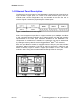
Table of Figures
5
© 2008 RuggedCom Inc. All rights reserved Rev100
Table of Figures
Figure 1: 19" Rack Front Mount (connectors at front).......................................................9
Figure 2: 19" Rack Rear Mount (connectors at rear) ........................................................9
Figure 3: RSG2300 Ethernet Port Layout ....................................................................... 10
Figure 4: Ethernet panel LEDs........................................................................................ 10
Figure 5: 1000LX SFP (mini-GBIC) Module and LC connector ...................................... 11
Figure 6: 1000LX GBIC connector .................................................................................. 11
Figure 7: 10FL ST connector ......................................................................................... 12
Figure 8: 100FX MTRJ connector .................................................................................. 12
Figure 9: 1000LX LC connector ...................................................................................... 12
Figure 10: 1000LX SC connector....................................................................................12
Figure 11: 1000LX ST connector .................................................................................... 12
Figure 12: RSG2300 LED Display Panel ........................................................................ 13
Figure 13: RSG2000 Family 19” Rack Mount Adapters.................................................. 15
Figure 14: Rack mount adapter mounting location ......................................................... 15
Figure 15: RSG2300 Panel / DIN RAIL mounting diagram (connectors at top) .............. 16
Figure 16: RSG2000 Series Philips Screw Terminal Block............................................. 17
Figure 17: RSG2000 Series Phoenix Plug Terminal Block ............................................. 17
Figure 18: Chassis Ground Connection .......................................................................... 18
Figure 19: AC Power supply wiring examples................................................................. 19
Figure 20: DC Power supply wiring examples ............................................................... 20
Figure 21: DC And AC power supply wiring examples .................................................. 21
Figure 22: Dielectric Strength (HIPOT) Testing .............................................................. 22
Figure 23: Failsafe Alarm Relay Wiring........................................................................... 23
Figure 24: Console port on display board ....................................................................... 24
Figure 25: RSG2000 Series Console cable .................................................................... 24
Figure 26: SFP Orientation for top and bottom row ports ............................................... 26
Figure 27: Locking latch location on GBIC optical modules........................................... 27
Figure 28: SFP Bail Latch Location................................................................................. 27
Figure 29: SFP Removal................................................................................................. 27
Figure 30: RSG2300 Mechanical Dimensions ................................................................ 34
Table of Tables
Table 1: Pluggable Fiber Transceiver Modules............................................................... 11
Table 2: Fixed Fiber Transceivers................................................................................... 12
Table 3: LED Display – Device status LED behavior definition....................................... 13
Table 4: Port Status LED behavior definition .................................................................. 14
Table 5: RSG2000 Series Power terminal block connection description ........................ 18
Table 6: RS232 over RJ45 console cable pin-out........................................................... 24
Table 7: Cabling categories and 1000BaseTx compliance defined. ............................... 25