RuggedSwitch® RSG2300 32-Port Managed Ethernet Switch with 4 Modular Gigabit Uplink Ports Installation Guide November 12, 2008 www.ruggedcom.com RuggedCom Inc.
Copyright COPYRIGHT © 2008 RuggedCom Inc. ALL RIGHTS RESERVED Dissemination or reproduction of this document, or evaluation and communication of its contents, is not authorized except where expressly permitted. Violations are liable for damages. All rights reserved, particularly for the purposes of patent application or trademark registration. This document contains proprietary information, which is protected by copyright. All rights are reserved.
Federal Communications Commission Radio Frequency Interference Statement This equipment has been tested and found to comply with the limits for a Class A digital device pursuant to Part 15 of the FCC Rules. These limits are designed to provide reasonable protection against harmful interference when the equipment is operated in a commercial environment.
Table of Contents Table of Contents Copyright........................................................................................................................... 2 Federal Communications Commission Radio Frequency Interference Statement ........... 3 Table of Contents.............................................................................................................. 4 Table of Figures ..........................................................................................................
Table of Figures Table of Figures Figure 1: 19" Rack Front Mount (connectors at front) ....................................................... 9 Figure 2: 19" Rack Rear Mount (connectors at rear) ........................................................ 9 Figure 3: RSG2300 Ethernet Port Layout ....................................................................... 10 Figure 4: Ethernet panel LEDs........................................................................................
Product Overview 1 Product Overview 1.1 Functional Overview The RuggedSwitch® RSG2300 is an industrially hardened, fully managed, modular Ethernet switch specifically designed to operate reliably in electrically harsh and climatically demanding utility substation and industrial environments.
Product Overview RuggedRated™ for Reliability in Harsh Environments • • • • • Immunity to EMI and heavy electrical surges o Zero-Packet-Loss™ Technology o Meets IEEE 1613 Class 2 (electric utility substations) o Exceeds IEC 61850-3 (electric utility substations) o Exceeds IEEE 61800-3 (variable speed drive systems) o Exceeds IEC 61000-6-2 (generic industrial environment) o Exceeds NEMA TS-2 (traffic control equipment) -40 to +85°C operating temperature (no fans) Conformal coated printed circuit boards (op
Product Overview 1.3 Mounting Flexibility RSG2000 series products have been designed with maximum mounting and display flexibility. Customers can order an RSG2000 series switch that can be mounted in a standard 19” rack, 1” DIN Rail, or directly onto a panel. For rack mount installations, the RSG2000 series can be ordered with connectors on the front panel or on the rear of the chassis.
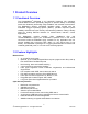
Product Overview 1.4 Ethernet Panel Description The Ethernet connector panel of the RSG2300 is organized into three banks of eight 10/100Tx copper ports, for a total of 24 fixed 10/100Tx ports, and four modular slots, whose configuration may be selected at the time the unit is ordered. Figure 3 shows the physical layout of these ports. Figure 3: RSG2300 Ethernet Port Layout Slots 1 and 2 support two-port fiber or copper modules up to 100Mbps, and Slots 3 and 4 support two-port modules up to 1Gbps.
Product Overview 1.4.1 Fiber Optic Transceiver Orientation and Connection Depending on the order code of the product, the RSG2300 can be equipped with several different types of fiber optic ports. The Transmit (TX) and Receive (RX) connections of each port must be properly connected and matched for proper link and operation. Modules populated on the top row of the device typically have locking mechanisms or tabs facing the top of the unit.
Product Overview Figure 7 through Figure 11 show front and top views of the fixed fiber transceiver modules supported by RuggedSwitch®. Note that when the daughter card containing transceiver modules is installed in the unit, most of the body of the module as shown in top views below will not be visible.
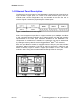
Product Overview 1.5 Display Panel Description RSG2000 series products are equipped with a versatile display panel, shown in Figure 12, which provides real-time status information for each port and for the chassis as a whole, to allow simple diagnostics and troubleshooting.
Product Overview The port LEDs can be cycled between three display modes: Status, Duplex, and Speed. Pushing the Mode button causes the display mode to be cycled.
Installation 2 Installation 2.1 Rack Mounting The RSG2000 family of products can be rack mounted using the included rack mount adapter assemblies shown in Figure 13. Secure the rack mount adapter to the front side of the chassis using the included black PAN head Philips screws in the positions shown in Figure 14. The entire chassis can then be mounted to a standard 19” rack.
Installation 2.2 Panel and DIN Rail Mounting RSG2000 series products can be ordered as panel/DIN mount chassis. Both options involve the use of the panel/DIN adapters to be mounted on each side of the chassis enclosure. The adapter allows for the chassis to be mounted on a standard 1” DIN rail using the grooves in the adapter, and secured using the included Philips screw. See Figure 15 for a PANEL/DIN mounting diagram.
Installation 2.3 Power Supply Wiring and Grounding The RSG2000 family supports dual redundant power supplies, “Power Supply 1” (PS1) and “Power Supply 2” (PS2). The connections for PS1, PS2 and the failsafe relay are located on the terminal block as shown in Figure 16 and Figure 17. RSG2000 products can be equipped with either a Philips Screw Terminal Block or a Phoenix Plug Terminal Block.
Installation The RSG2000 Family chassis ground connection, shown in Figure 18, uses a #632 screw. It is recommended to terminate the ground connection in a #6 ring lug, and to use a torque setting not exceeding 15 in·lbs (1.7 Nm). #6-32 screw with ext. washer. #6 ring lug stainless steel standoff Figure 18: Chassis Ground Connection Terminal Number Description Usage PS1 Live / + is connected to the positive (+) terminal if the power source is DC or to the (Live) terminal if the power source is AC.
Installation 2.3.1 AC Power Supply Wiring Examples Figure 19: AC Power supply wiring examples Notes: • • • 125/230VAC rated equipment: A 250VAC appropriately rated circuit breaker must be installed. Equipment must be installed according to the applicable country wiring codes. When equipped with two HI voltage power supplies, independent AC sources can be used to power the product for greater redundancy. 19 © 2008 RuggedCom Inc.
Installation 2.3.2 DC Power Supply Wiring Examples Figure 20: DC Power supply wiring examples Notes: • • • • 125/250VDC rated equipment: A 300VDC appropriately rated circuit breaker must be installed. A circuit breaker is not required for 12-24 or 48 VDC rated power supplies. For dual DC power supplies, separate circuit breakers must be installed and separately identified. Equipment must be installed according to the applicable country wiring codes. 20 Rev100 © 2008 RuggedCom Inc.
Installation 2.3.3 Dual Power Supplies – DC and AC Inputs Figure 21: DC And AC power supply wiring examples Notes: • • • • • 125/250VDC rated equipment: A 300VDC appropriately rated circuit breaker must be installed. 110/230VAC rated equipment: A 250VAC appropriately rated circuit breaker must be installed. A circuit breaker is not required for 12-24 or 48VDC rated power supplies. Separate circuit breakers must be installed and separately identified.
Installation 2.4 Dielectric Strength (HIPOT) Testing For dielectric strength (HIPOT) testing in the field, users must remove the metal jumper located across terminals 2, 4, and 6 of the power supply terminal block. This metal jumper connects transient suppression circuitry to chassis ground and must be removed in order to avoid damage to transient suppression circuitry during HIPOT testing. Figure 22 shows the proper HIPOT test connections and should be followed to avoid damage to the device.
Installation 2.5 Failsafe Alarm Relay Wiring and Specifications The “Failsafe” output relay is provided to signal critical error conditions that may occur on RS2000 series products. The contacts are energized upon power-up of the unit and remain energized unless a critical error occurs. The proper relay connections are shown in Figure 23. Control of this output is user selectable and can be programmed via the Rugged Operating System (ROS).
Installation 2.6 Console Port Wiring An RS232 console port for configuration and management of the device is located on the LED display module shown in Figure 24. This port is intended to be a temporary connection during initial configuration or troubleshooting and allows for direct serial access to the management console. The connection is made using the DB9-Female to RJ45 console cable included in the device packaging shown in Figure 25.
Installation 2.7 Gigabit Ethernet 1000Base-TX Cabling Recommendations The IEEE 802.3ab Gigabit Ethernet standard defines 1000 Mbit/s Ethernet communications over distances of up to 100 meters using all 4 pairs in category 5 (or higher) balanced unshielded twisted-pair cabling.
Installation 2.8 Pluggable optics – Installation, removal, and precautions The RSG2300 can be ordered with two pluggable optical form factors: SFP (Small Form-factor Pluggable), and GBIC (GigaBit Interface Converter). SFP and GBIC modules can be safely inserted and removed while the chassis is powered and operating – a feature also referred to as “hot-swappable”. Nevertheless, when inserting or removing optics there are several precautions that should be taken.
Installation Both SFP and GBIC modules should gently slide into their ports and should lock in place when fully inserted. Dust covers should be in place when installing the modules, and should always be in place when cables are not connected. Diagrams of both SFP and GBIC modules are provided in Table 1 as a guide to the orientation of each type. 2.8.2 GBIC Module Removal GBIC modules have two locking latches, one on either side of the module, as shown in Figure 27.
Technical Specifications 3 Technical Specifications 3.1 Power Supply Specifications Power Supply Type Input Range Min Max Fuse Rating 12 – 24 VDC 10 VDC 36 VDC 6.3A(F)2 48 VDC 36 VDC 59 VDC 2A(T)2 HI (125/250 VDC)1 HI (110/230 VAC)1 88 VDC 85 VAC 300 VDC 265 VAC 2A(T)1,2 Max. Power Consumption3 25W Notes: 1. This is the same power supply for both AC and DC. 2. (F) Denotes fast-acting fuse, (T) denotes time-delay fuse 3. Power consumption varies based on configuration.
Technical Specifications 3.4 Copper Ethernet Port Specifications The RSG2300 features a fixed set of three fixed banks of eight 10/100Tx copper ports each, and can be ordered with additional 10/100Tx ports in slots 1 and 2, and 10/100/1000Tx ports in slots 3 and 4.
Technical Specifications FX04 SM ST 9/125 1310 -15 -8 -32 -3 20 17 FX05 FX06 FX07 FX08 FX09 FX10 SM SM SM SM SM SM SC LC SC LC SC LC 9/125 9/125 9/125 9/125 9/125 9/125 1300 1310 1310 1310 1310 1310 -15 -15 -5 -5 0 0 -8 -8 0 0 5 5 -31 -34 -34 -35 -37 -37 -7 -7 -3 -3 0 0 20 20 50 50 90 90 16 19 29 30 37 37 3.5.3 Gigabit Ethernet (1000Mbps) Optical Specifications Fixed Gigabit Transceivers Order Code Mode Connector Type Cable Type (um) Tx λ (typ.
Technical Specifications 3.6 Type Test Specifications 3.6.1 IEEE 1613 (C37.90.x) EMI Immunity Type Tests Test Description IEEE C37.90.3 ESD IEEE C37.90.2 Radiated RFI IEEE C37.90.1 Fast Transient IEEE C37.90.1 Oscillatory Enclosure Contact Enclosure Air Enclosure ports Signal ports D.C. Power ports A.C. Power ports Earth ground ports1 Signal ports D.C. Power ports A.C. Power ports IEEE C37.90 H.V. Impulse IEEE C37.90 Dielectric Strength Signal ports D.C. Power ports A.C.
Technical Specifications IEC 61000-4-8 Magnetic Field Enclosure ports D.C. Power ports IEC 61000-4-29 Voltage Dips & Interrupts A.C. Power ports IEC 61000-4-11 Signal ports IEC 61000-4-12 Damped Oscillatory D.C. Power ports A.C. Power ports IEC 61000-4-16 Mains Frequency Voltage IEC 61000-4-17 Ripple on D.C. Power Supply IEC 60255-5 Dielectric Strength IEC 60255-5 H.V. Impulse Signal ports D.C. Power ports D.C. Power ports Signal ports D.C. Power ports A.C. Power ports Signal ports D.C.
Technical Specifications 3.6.3 Environmental Type Tests Test IEC 60068-2-1 IEC 60068-2-2 IEC 60068-2-30 IEC 60255-21-1 IEC 60255-21-2 Description Cold Temperature Dry Heat Humidity (Damp Heat, Cyclic) Vibration Shock Test Levels Test Ad Test Bd Test Db Tests Fc Tests Ea -40°C, 16 Hours +85°C, 16 Hours 95% (non-condensing), 55°C , 6 cycles 2g @ (10 - 150) Hz 30g @ 11mS Severity Levels N/A N/A N/A Class 21 Class 21 Note: 1.
Technical Specifications 3.8 Mechanical Specifications Parameter Value Comments Dimensions 18.29 x 12.14 x 1.75 in (464.57 × 308.36 × 44.45 mm) 10 lb (4.5 kg) 18AWG galvanized steel (Length x Width x Height) with mounting brackets installed Weight Enclosure Figure 30: RSG2300 Mechanical Dimensions 34 Rev100 © 2008 RuggedCom Inc.
Agency Approvals 4 Agency Approvals Agency Standards CSA C22.2 No. 60950, UL 60950 CSA CE EN 60950, EN 61000-6-2 FCC CISPR FCC Part 15, Class A EN55022, Class A 21 CFR Chapter 1, Subchapter J EN60825-1:1994 + A11:1996 + A2:2001 FDA/CDRH IEC/EN Comments Passed CE Compliance is claimed via Declaration of Self Conformity Route Passed Passed Passed Passed 5 Warranty RuggedCom warrants this product for a period of five (5) years from date of purchase. For warranty details, visit http://www.ruggedcom.