
User manual


71
Industrial PDA
(EDA)
Automotive PC
Tablet PC
IEIMobile
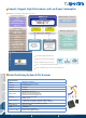
Introduction
A vehicle bus protocol is a specialized internal communications network that interconnects components inside a vehicle. It also provides
interface for users to acquire vehicle data for diagnostic or cruise information such as vehicle speed, engine loading, engine R.P.M and
fuel level. OBD-II supports more than 79 kinds of vehicle information.
Vehicle Speed
Engine Loading
Engine R.P.M
Fuel Level :
More than 79 items!
J1962 Interface
OBD-II Cable
Vehicle Bus Protocol (OBD-II)
OBD-II
J1939
FMS
Firmware
Application
OS & Drivers
Main
CPU
MCU
CAN-bus 2.0b
Physical Connection Interface
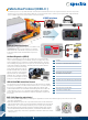
The vehicle bus connection is mostly based on CAN-bus 2.0b
signaling via a specific connection interface. For example,
OBD-II defines the J1962 female 16-pin (2x8) connector as
its physical interface while J1939 defines the 9-pin round
connector.
OBD-II/J1939/FMS Vehicle Bus Protocol
The vehicle bus protocol deals with special request for data transmission reliability
and quality on vehicle bus. The MCU inside the iKarPC acts as a converter among
these protocols. The OBD-II is mostly for small car diagnostics while the SAE
J1939 is implemented for off-road vehicles with diesel engines and the FMS is for
commercial trucks or buses. As a standard offering, IEIMobile supports OBD-II
protocol. Other protocols such as FMS and J1939 are supported on a optional by
project basis.
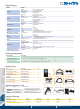
On-Board Diagnostics (OBD-II)
OBD-II is a standard that specifies the type of diagnostic connector and its pin-
out, the electrical signaling protocols available, and the messaging format. There
are five signalling protocols currently in use with the OBD-II interface. Any given
vehicle will likely only implement one of the protocols. The iKarPC supports ISO
15765 CAN (250 kBit/s or 500 kBit/s). The CAN protocol is a popular standard
outside of the US automotive industry
and is making significant in-roads into
the OBD-II market share. By 2008, all
vehicles sold in the US are required to
implement CAN, thus eliminating the
ambiguity of the existing five signaling
protocols. The CAN signals are via pin-
6 and pin-14 of the OBD-II connector.
Pin
Description
1
-
2
Bus positive Line of SAE-J1850 PWM and SAE-1850 VPW
3
-
4
-
5
-
6
CAN high (ISO 15765-4 and SAE-J2284)
7
K line of ISO 9141-2 and ISO 14230-4
8
-
9
-
10
Bus negative Line of SAE-J1850 PWM only (not SAE-1850 VPW)
11
-
12
-
13
-
14
CAN low (ISO 15765-4 and SAE-J2284)
15
L line of ISO 9141-2 and ISO 14230-4
16
-
SAE J1939 (Spport by project basis)
●SAE J1939 has been adopted widely by diesel engines. Applications of J1939 now include off-highway, truck, bus, and even some
passenger car applications.
●SAE J1939 defines five layers in the 7-layer OSI network model, and this includes the
CAN 2.0b specification (using only the 29-bit/"extended" identifier) for the physical and
data-link layers. The session and presentation layers are not part of the specification.
●All J1939 packets contain eight bytes of data and a standard header which contains
an index called PGN (Parameter Group Number). J1939 defines standard PGNs to
encompass a wide range of automotive, agricultural, construction, marine and off-road
vehicle purposes.
Spectra GmbH & Co. KG
www.spectra.de spectra@spectra.de
Spectra (Schweiz) AG
www.spectra.ch info@spectra.ch
Niederlassung Österreich
www.spectra-austria.at info@spectra-austria.at