GS-2124C User's Manual 24 Gigabit L2 Managed Switch Release 0.98 2005, RubyTech Corporation. All rights reserved. All brand and product names are trademarks or registered trademarks of their respective companies.
The information in this document is subject to change without notice. Unless the explicit written permission of RubyTech Corporation, this document in whole or in part shall not be replicated or modified or amended or transmitted, in any from, or by any means manual, electric, electronic, electromagnetic, mechanical, optical or otherwise for any purpose.
DISCLAIMER. EXCEPT AS PROVIDED ABOVE, THE SOFTWARE IS PROVIDED “AS IS ” AND RUBYTECH AND ITS LICENSORS MAKE NO WARRANTIES, EXPRESS OR IMPLIED, WITH REPSECT TO THE SOFTWARE AND DOCUMENTAITON. RUBYTECH AND ITS LICENSORS DISCLAIM ALL OTHER WARRANTIES, INCLUSIVE OF WITHOUT LIMITATION, IMPLIED WARRANTIES OR MERCHANTABILITY, FITNESS FOR A PARTICULAR PURPOSE AND NONINFRINGEMENT.
Table of Contents CAUTION ------------------------------------------------------------------------------------- VIII ELECTRONIC EMISSION NOTICES -------------------------------------------------------- VIII CHAPTER 1. INTRODUCTION ---------------------------------------------------------- 2 1-1. OVERVIEW OF GS-2124C ------------------------------------------------------------ 2 1-2. CHECKLIST ------------------------------------------------------------------------------- 4 1-3.
3-5. QOS(QUALITY OF SERVICE) CONFIGURATION ----------------------------------- 57 3-6. SNMP CONFIGURATION ------------------------------------------------------------- 67 3-7. IGMP SNOOPING --------------------------------------------------------------------- 69 3-8. MAX. PACKET LENGTH --------------------------------------------------------------- 71 3-9. DHCP BOOT -------------------------------------------------------------------------- 72 3-10.
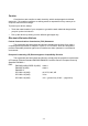
Revision History Release Date Revision 0.
vii
Caution Circuit devices are sensitive to static electricity, which can damage their delicate electronics. Dry weather conditions or walking across a carpeted floor may cause you to acquire a static electrical charge. To protect your device, always: • Touch the metal chassis of your computer to ground the static electrical charge before you pick up the circuit device. • Pick up the device by holding it on the left and right edges only.
About this user’s manual In this user’s manual, it will not only tell you how to install and connect your network system but configure and monitor the GS-2124C through the built-in CLI and web by RS-232 serial interface and Ethernet ports step-by-step. Many explanation in detail of hardware and software functions are shown as well as the examples of the operation for web-based interface and command-line interface (CLI).
GS-2124C User Manual 1. Introduction 1-1. Overview of GS-2124C GS-2124C, a 24-port Gigabit L2 Managed Switch, is a standard switch that meets all IEEE 802.3/u/x/z Gigabit, Fast Ethernet specifications. The switch included 22-Port 10/100/1000Mbps TP and 2-Port Gigabit TP/SFP Fiber management Ethernet switch. The switch can be managed through RS-232 serial port via directly connection, or through Ethernet port using CLI or Web-based management unit, associated with SNMP agent.
GS-2124C User Manual • Key Features in the Device QoS: Support Quality of Service by the IEEE 802.1P standard. There are two priority queue and packet transmission schedule using Weighted Round Robin (WRR). User-defined weight classification of packet priority can be based on either a VLAN tag on packet or a user-defined port priority. Spanning Tree: Support IEEE 802.1D, IEEE 802.1w (RSTP: Rapid Spanning Tree Protocol) and IEEE 802.1s (MSTP: Multiple Spanning Tree Protocol) standards.
GS-2124C User Manual 1-2. Checklist Before you start installing the switch, verify that the package contains the following: GS-2124C 24 Gigabit L2 Managed Switch Modules (optional) Mounting Accessory (for 19” Rack Shelf) This User's Manual in CD-ROM AC Power Cord RS-232 Cable Please notify your sales representative immediately if any of the aforementioned items is missing or damaged. 1-3.
GS-2124C User Manual • Supports 802.
GS-2124C User Manual 1-4. View of GS-2124C Fig. 1-1 Full View of 24 Gigabit L2 Managed Switch 1-4-1. User Interfaces on the Front Panel (Button, LEDs and Plugs) There are 24 TP Gigabit Ethernet ports and 2 SFP fiber ports for optional removable modules on the front panel of the switch. LED display area, locating on the left side of the panel, contains a Power LED, which indicates the power status and 24 ports working status of the switch.
GS-2124C User Manual • LED Indicators LED POWER CPU LED Color System LED Green Green Function Lit when +5V DC power is on and good Blinks when CPU is activity 10/100/1000Ethernet TP Port 1 to 24 LED Lit when connection with remote device is good LINK/ACT Green Blinks when any traffic is present Off when cable connection is not good Lit green when 1000Mbps speed is active Green/ Lit ember when 100Mbps speed is active 10/100/1000Mbps Ember Off when 10Mbps speed is active 1000SX/LX Gigabit Fiber Port 23,
GS-2124C User Manual 1-5. View of the Optional Modules In the switch, Port 23~24 includes two types of media --- TP and SFP Fiber (LC, BiDi LC…); this port supports 10/100/1000Mbps TP or 1000Mbps SFP Fiber with auto-detected function. 1000Mbps SFP Fiber transceiver is used for highspeed connection expansion; nine optional SFP types provided for the switch are listed below: 1000Mbps LC, MM, SFP Fiber transceiver (SFP.0LC.202) 1000Mbps LC, SM 10km, SFP Fiber transceiver (SFP.0LC.212.
GS-2124C User Manual 2. Installation 2-1. Starting GS-2124C Up This section will give users a quick start for: - Hardware and Cable Installation - Management Station Installation - Software booting and configuration 2-1-1.
GS-2124C User Manual • TP Port and Cable Installation ⇒ In the switch, TP port supports MDI/MDI-X auto-crossover, so both types of cable, straight-through (Cable pin-outs for RJ-45 jack 1, 2, 3, 6 to 1, 2, 3, 6 in 10/100M TP; 1, 2, 3, 4, 5, 6, 7, 8 to 1, 2, 3, 4, 5, 6, 7, 8 in Gigabit TP) and crossed-over (Cable pin-outs for RJ-45 jack 1, 2, 3, 6 to 3, 6, 1, 2) can be used. It means you do not have to tell from them, just plug it. ⇒ Use Cat.
GS-2124C User Manual 2-1-2-1. Cabling Requirements for TP Ports ⇒ For Fast Ethernet TP network connection The grade of the cable must be Cat. 5 or Cat. 5e with a maximum length of 100 meters. ⇒ Gigabit Ethernet TP network connection The grade of the cable must be Cat. 5 or Cat. 5e with a maximum length of 100 meters. Cat. 5e is recommended. 2-1-2-2. Cabling Requirements for 1000SX/LX SFP Module It is more complex and comprehensive contrast to TP cabling in the fiber media.
GS-2124C User Manual 2-1-2-3. Switch Cascading in Topology • Takes the Delay Time into Account Theoretically, the switch partitions the collision domain for each port in switch cascading that you may up-link the switches unlimitedly. In practice, the network extension (cascading levels & overall diameter) must follow the constraint of the IEEE 802.3/802.3u/802.3z and other 802.1 series protocol specifications, in which the limitations are the timing requirement from physical signals defined by 802.
GS-2124C User Manual Case1: All switch ports are in the same local area network. Every port can access each other (See Fig. 2-2). Fig. 2-2 No VLAN Configuration Diagram If VLAN is enabled and configured, each node in the network that can communicate each other directly is bounded in the same VLAN area. Here VLAN area is defined by what VLAN you are using. The switch supports both port-based VLAN and tag-based VLAN. They are different in practical deployment, especially in physical location.
GS-2124C User Manual Case 2b: Port-based VLAN (See Fig.2-4). Fig. 2-4 Port-based VLAN Diagram 1. VLAN1 members could not access VLAN2, VLAN3 and VLAN4 members. 2. VLAN2 members could not access VLAN1 and VLAN3 members, but they could access VLAN4 members. 3. VLAN3 members could not access VLAN1, VLAN2 and VLAN4. 4. VLAN4 members could not access VLAN1 and VLAN3 members, but they could access VLAN2 members. Case3a: The same VLAN members can be at different switches with the same VID (See Fig. 2-5). Fig.
GS-2124C User Manual 2-1-3. Configuring the Management Agent of GS-2124C We offer you three ways to startup the switch management function. They are RS-232 console, CLI, and Web. Users can use any one of them to monitor and configure the switch. You can touch them through the following procedures.
GS-2124C User Manual 2-1-3-1. Configuring the Management Agent of GS-2124C through the Serial RS-232 Port To perform the configuration through RS-232 console port, the switch’s serial port must be directly connected to a DCE device, for example, a PC, through RS-232 cable with DB-9 connector. Next, run a terminal emulator with the default setting of the switch’s serial port. With this, you can communicate with the switch. In the switch, RS-232 interface only supports baud rate 57.
GS-2124C User Manual • Set IP Address, Subnet Mask and Default Gateway IP Address Please refer to Fig. 2-6 Console Management for details about the ex-factory setting. They are default setting of IP address. You can first either configure your PC IP address or change IP address of the switch, next to change the IP address of default gateway and subnet mask. For example, your network address is 10.1.1.0, and subnet mask is 255.255.255.0. You can change the switch’s default IP address 192.168.1.1 to 10.1.1.
GS-2124C User Manual 2-1-3-2. Configuring the Management Agent of GS-2124C through the Ethernet Port There are three ways to configure and monitor the switch through the switch’s Ethernet port. They are CLI, Web browser and SNMP manager. The user interface for the last one is NMS dependent and does not cover here. We just introduce the first two types of management interface. 24 Gigabit L2 Managed Switch Default IP Setting: IP = 192.168.1.1 Subnet Mask = 255.255.255.0 Default Gateway = 192.168.1.
GS-2124C User Manual Fig. 2-9 the Login Screen for Web 2-1-4. IP Address Assignment For IP address configuration, there are three parameters needed to be filled in. They are IP address, Subnet Mask, Default Gateway and DNS. IP address: The address of the network device in the network is used for internetworking communication. Its address structure looks is shown in the Fig. 2-10. It is “classful” because it is split into predefined address classes or categories.
GS-2124C User Manual With the classful addressing, it divides IP address into three classes, class A, class B and class C. The rest of IP addresses are for multicast and broadcast. The bit length of the network prefix is the same as that of the subnet mask and is denoted as IP address/X, for example, 192.168.1.0/24. Each class has its address range described below. Class A: Address is less than 126.255.255.255. There are a total of 126 networks can be defined because the address 0.0.0.
GS-2124C User Manual Class D and E: Class D is a class with first 4 MSB (Most significance bit) set to 1-1-1-0 and is used for IP Multicast. See also RFC 1112. Class E is a class with first 4 MSB set to 1-1-1-1 and is used for IP broadcast. According to IANA (Internet Assigned Numbers Authority), there are three specific IP address blocks reserved and able to be used for extending internal network. We call it Private IP address and list below: Class A Class B Class C 10.0.0.0 --- 10.255.255.255 172.16.0.
GS-2124C User Manual In this diagram, you can see the subnet mask with 25-bit long, 255.255.255.128, contains 126 members in the sub-netted network. Another is that the length of network prefix equals the number of the bit with 1s in that subnet mask. With this, you can easily count the number of IP addresses matched. The following table shows the result. Prefix Length No. of IP matched No.
GS-2124C User Manual For different network applications, the subnet mask may look like 255.255.255.240. This means it is a small network accommodating a maximum of 15 nodes in the network. Default gateway: For the routed packet, if the destination is not in the routing table, all the traffic is put into the device with the designated IP address, known as default router. Basically, it is a routing policy. The gateway setting is used for Trap Events Host only in the switch.
GS-2124C User Manual 2-2. Typical Applications The GS-2124C implements 24 Gigabit Ethernet TP ports with auto MDIX and two slots for the removable module supporting comprehensive fiber types of connection, including LC and BiDi-LC SFP modules. For more details on the specification of the switch, please refer to Appendix A. The switch is suitable for the following applications. Central Site/Remote site application is used in carrier or ISP (See Fig.
GS-2124C User Manual Fig. 2-13 Peer-to-peer Network Connection Fig.
GS-2124C User Manual 3. Operation of Web-based Management This chapter instructs you how to configure and manage the GS-2124C through the web user interface it supports, to access and manage the 22-Port 10/100/1000Mbps TP and 2-Port Gigabit TP/SFP Fiber management Ethernet switch.
GS-2124C User Manual Fig. 3-1 3-1. Web Management Home Overview After you login, the switch shows you the system information as Fig. 3-2. This page is default and tells you the basic information of the system, including “Model Name”, “System Description”, “Location”, “Contact”, “Device Name”, “System Up Time”, “Current Time”, “BIOS Version”, “Firmware Version”, “Hardware-Mechanical Version”, “Series Number”, “Host IP Address”, “Host Mac Address”, “Device Port”, “RAM Size” and “Flash Size”.
GS-2124C User Manual • The Information of Page Layout On the top side, it shows the front panel of the switch. In the front panel, the linked ports will display green; as to the ports, which are link off, they will be dark. For the optional modules, the slot will show only a cover plate if no module exists and will show a module if a module is present. The image of module depends on the one you inserted. The same, if disconnected, the port will show just dark, if linked, green.
GS-2124C User Manual Root System Port Mirror Bandwidth QoS SNMP IGMP Snooping Max. Packet Length DHCP Boot VLAN MAC Table GVRP STP Trunk 802.
GS-2124C User Manual 3-1-1. System Information Function name: System Information Function description: Show the basic system information. Parameter description: Model name: The model name of this device. System description: As it is, this tells what this device is. Here, it is “L2 Managed Switch”. Location: Basically, it is the location where this switch is put. User-defined. Contact: For easily managing and maintaining device, you may write down the contact person and phone here for getting help soon.
GS-2124C User Manual Host IP address: The IP address of the switch. Host MAC address: It is the Ethernet MAC address of the management agent in this switch. Device Port: Show all types and numbers of the port in the switch. RAM size: The size of the DRAM in this switch. Flash size: The size of the flash memory in this switch.
GS-2124C User Manual 3-1-2. IP Configuration IP configuration is one of the most important configurations in the switch. Without the proper setting, network manager will not be able to manage or view the device. The switch supports both manual IP address setting and automatic IP address setting via DHCP server. When IP address is changed, you must reboot the switch to have the setting taken effect and use the new IP to browse for web management and CLI management. Fig.
GS-2124C User Manual IP address: Users can configure the IP settings and fill in new values if users set the DHCP function “Disable”. Then, click button to update. When DHCP is disabled, Default: 192.168.1.1 If DHCP is enabled, this field is filled by DHCP server and will not allow user manually set it any more.
GS-2124C User Manual DNS: It is Domain Name Server used to serve the translation between IP address and name address. The switch supports DNS client function to re-route the mnemonic name address to DNS server to get its associated IP address for accessing Internet. User can specify a DNS IP address for the switch. With this, the switch can translate a mnemonic name address into an IP address. There are two ways to specify the IP address of DNS.
GS-2124C User Manual 3-1-3. Time Configuration The switch provides manual and automatic ways to set the system time via NTP. Manual setting is simple and you just input “Year”, “Month”, “Day”, “Hour”, “Minute” and “Second” within the valid value range indicated in each item. If you input an invalid value, for example, 61 in minute, the switch will clamp the figure to 59. NTP is a well-known protocol used to synchronize the clock of the switch system time over a network.
GS-2124C User Manual NTP: NTP is Network Time Protocol and is used to sync the network time based Greenwich Mean Time (GMT). If use the NTP mode and select a built-in NTP time server or manually specify an user-defined NTP server as well as Time Zone, the switch will sync the time in a short after pressing button. Though it synchronizes the time automatically, NTP does not update the time periodically without user’s processing. Time Zone is an offset time off GMT.
GS-2124C User Manual Day Light Saving End : This is used to set when to stop performing the daylight saving time. Mth: Range is 1 ~ 12. Default: 1 Day: Range is 1 ~ 31. Default: 1 Hour: Range is 0 ~ 23. Default: 0 Fig.
GS-2124C User Manual 3-1-4. Account Configuration In this function, only administrator can create, modify or delete the username and password. Administrator can modify other guest identities’ password without confirming the password but it is necessary to modify the administrator-equivalent identity. Guest-equivalent identity can modify his password only. Please note that you must confirm administrator/guest identity in the field of Authorization in advance before configuring the username and password.
GS-2124C User Manual 3-1-5. Management Policy Through the management security configuration, the manager can do the strict setup to control the GS-2124C and limit the user to access this switch. The following rules are offered for the manager to manage the GS-2124C: Rule 1) : When no lists exists, then it will accept all connections.
GS-2124C User Manual Function name: Management Security Configuration Function description: GS-2124C offers Management Security Configuration function. With this function, the manager can easily control the mode that the user connects to GS-2124C. According to the mode, users can be classified into two types: Those who are able to connect to GS-2124C (Accept) and those who are unable to connect to GS-2124C (Deny).
GS-2124C User Manual IP Range: GS-2124C supports two kinds of options for managed valid IP Range, including “Any” and “Custom”. Default is “Any”. In case that” Custom” had been chosen, you can assigned effective IP range. The valid range is 0.0.0.0~255.255.255.255. Incoming Port: GS-2124C supports two kinds of options for managed valid Port Range, including “Any” and “Custom”. Default is “Any”.
GS-2124C User Manual 3-2. Port Configuration Four functions, including Port Status, Port Configuration, Simple Counter and Detail Counter are contained in this function folder for port monitor and management. Each of them will be described in detail orderly in the following sections. Port Configuration Status Configuration Simple Counter Detail Counter 3-2-1.
GS-2124C User Manual Function name: Port Status Function Description: Report the latest updated status of all ports in this switch. When any one of the ports in the switch changes its parameter displayed in the page, it will be automatically refreshed the port current status about every 5 seconds. Parameter Description: Port No: Display the port number. The number is 1 – 24. Both port 23 and 24 are optional modules. Media: Show the media type adopted in all ports.
GS-2124C User Manual Speed / Duplex Mode: Display the speed and duplex of all port. There are three speeds 10Mbps, 100Mbps and 1000Mbps supported for TP media, and the duplex supported is half duplex and full duplex. If the media is 1Gbps fiber, it is 1000Mbps supported only. The status of speed/duplex mode is determined by 1) the negotiation of both local port and link partner in “Auto Speed” mode or 2) user setting in “Force” mode. The local port has to be preset its capability.
GS-2124C User Manual Fig. 3-9 Parameter description of Port 23 and Port24: Connector Type: Display the connector type, for instance, UTP, SC, ST, LC and so on. Fiber Type: Display the fiber mode, for instance, Multi-Mode, Single-Mode. Tx Central Wavelength: Display the fiber optical transmitting central wavelength, for instance, 850nm, 1310nm, 1550nm and so on. Baud Rate: Display the maximum baud rate of the fiber module supported, for instance, 10M, 100M, 1G, 10G and so on.
GS-2124C User Manual Vendor SN (Serial Number): Show the serial number assigned by the manufacturer. Date Code: Show the date this SFP module was made. Temperature: Show the current temperature of SFP module. Vcc: Show the working DC voltage of SFP module. Mon1(Bias) mA: Show the Bias current of SFP module. Mon2(TX PWR): Show the transmit power of SFP module. Mon3(RX PWR): Show the receiver power of SFP module.
GS-2124C User Manual 3-2-2. Port Configuration Port Configuration is applied to change the setting of each port. In this configuration function, you can set/reset the following functions. All of them are described in detail below. Fig. 3-10 Function name: Port Configuration Function description: It is used to set each port’s operation mode. The switch supports 3 parameters for each port. They are state, mode and flow control.
GS-2124C User Manual Mode: Set the speed and duplex of the port. In speed, if the media is 1Gbps fiber, it is always 1000Mbps and the duplex is full only. If the media is TP, the Speed/Duplex is comprised of the combination of speed mode, 10/100/1000Mbps, and duplex mode, full duplex and half duplex. The following table summarized the function the media supports.
GS-2124C User Manual 3-2-3. Simple Counter The function of Simple Counter collects any information and provides the counting about the traffic of the port, no matter the packet is good or bad. In the Fig. 3-11, the window can show all ports’ counter information at the same time. Each data field has 12-digit long. If the counting is overflow, the counter will be reset and restart counting. The data is updated every time interval defined by the user. The valid range is 3 to 10 seconds.
GS-2124C User Manual Rx Packet: The counting number of the packet received. Tx Collision: Number of collisions transmitting frames experienced. Rx Error Packet: Number of bad packets received.
GS-2124C User Manual 3-2-4. Detail Counter The function of Detail Counter collects any information and provides the counting about the traffic of the port, no matter the packet is good or bad. In the Fig. 3-12, the window can show only one port counter information at the same time. To see another port’s counter, you have to pull down the list of Select, then you will see the figures displayed about the port you had chosen. Each data field has 12-digit long.
GS-2124C User Manual Rx Low Priority Packets: Number of Rx packets classified as low priority. Rx Broadcast: Show the counting number of the received broadcast packet. Rx Multicast: Show the counting number of the received multicast packet. Tx Packets: The counting number of the packet transmitted. TX Octets: Total transmitted bytes. Tx High Priority Packets: Number of Tx packets classified as high priority. Tx Low Priority Packets: Number of Tx packets classified as low priority.
GS-2124C User Manual Tx 65-127 Bytes: Number of 65 ~ 126-byte frames in good and bad packets transmitted. Tx 128-255 Bytes: Number of 127 ~ 255-byte frames in good and bad packets transmitted. Tx 256-511 Bytes: Number of 256 ~ 511-byte frames in good and bad packets transmitted. Tx 512-1023 Bytes: Number of 512 ~ 1023-byte frames in good and bad packets transmitted. Tx 1024-Bytes: Number of 1024-max_length-byte frames in good and bad packets transmitted.
GS-2124C User Manual 3-3. Mirror Function name: Mirror Configuration Function description: Mirror Configuration is to monitor the traffic of the network. For example, we assume that Port A and Port B are Monitoring Port and Monitored Port respectively, thus, the traffic received by Port B will be copied to Port A for monitoring. Note: When configuring the mirror function, you should avoid setting a port to be a sniffer port and aggregated port at the same time. It will cause something wrong.
GS-2124C User Manual 3-4. Bandwidth Management Function name: Bandwidth Management Function description: Bandwidth Management function is used to set up the limit of Ingress and Egress bandwidth for each port. Note: Each port of the switch owns 16KB packet buffer. The packet buffer size will be reduced when the bandwidth rate limitation is enabled, which may cause that jumbo frame cannot be forwarded. Please avoid enabling jumbo frame and bandwidth rating functions at the same time. Fig.
GS-2124C User Manual Broadcast & Multicasat for Ingress Rate Limiting (Policing): Set up the limit of Ingress bandwidth for the port you choose. Incoming traffic will be discarded if the rate exceeds the value you set up in Data Rate field. The format of the packet limits to broadcast and multicast. Valid range is 0~1000. All Traffic for Egress Rate Limiting(Shaping): Set up the limit of Egress bandwidth for the port you choose.
GS-2124C User Manual 3-5. QoS(Quality of Service) Configuration The switch offers powerful 5 kinds of QoS functions. There are Per Port Priority that you can assign each port to different precedence, VLAN Tag priority that can make precedence of 8 priorities, IP TOS Classification, IP TCP/UDP Port Classification and IP DiffServe Classification. In Quality of Service (QoS) Configuration, there is one option named” Default Class”.
GS-2124C User Manual Function name: Per Port Priority Function description: We can assign QoS Priority, including High and Low for each port. For example, if we transmit IP packets from Port 2 and Port 3 at the speed of 1Gbps to Port 1, and set the Class of Port 2 as High and Port 3 as Low, then the packets of Port 3 will be dropped when the congestion happens because Port 2 owns higher precedence of transmitting packets.
GS-2124C User Manual Function name: VLAN Tag Priority Function description: In vlan tag, there are 3 bits belonging to priority. According to these 3 bits, we could arrange 8 traffics –0 0 0, 0 0 1, 0 1 0, 0 1 0, 1 0 0, 1 0 1, 1 1 0, 1 1 1. We can set High priority or Low priority for each traffic class. For instance, if we let VLAN-tagged priority 0 0 0 be high priority and VLAN-tagged priority 0 0 1 be Low Priority, and then make port 1, 2, 3 be in the vlan 2.
GS-2124C User Manual Bit 0, Bit 1, Bit 2: According to the arrangement of VLAN-tagged priority, it can form 8 kinds of traffics, including 0 0 0, 0 0 1, 0 1 0, 0 1 0, 1 0 0, 1 0 1, 1 1 0 and 1 1 1. Class: 8 kinds of traffic as mentioned above, user can set up High Priority or Low Priority for each port respectively.
GS-2124C User Manual Function name: IP ToS Classification Function description: Another QoS function is the application of Layer 3 on network framework. We focus on TOS field of IP header. There are three bits in TOS field. We means bit 2~4 of TOS field that we will use. According to these 3 bits, we could arrange 8 traffics –0 0 0, 0 0 1, 0 1 0, 0 1 0, 1 0 0, 1 0 1, 1 1 0, 1 1 1. As long as we change bit 5~7 of TOS field of IP header, we will create the 8 traffic packets we meant before.
GS-2124C User Manual Bit 0, Bit 1, Bit 2: According to the arrangement of Bit 5 ~ Bit 7 in TOS Field of IP Header, it can form 8 kinds of traffics, including 0 0 0, 0 0 1, 0 1 0, 0 1 0, 1 0 0, 1 0 1, 1 1 0 and 1 1 1. Class: 8 kinds of traffic as mentioned above, user can set up High Priority or Low Priority for each port respectively.
GS-2124C User Manual Function name: IP TCP/UDP Port Classification Function description: In L4 QoS Configuration, you can enter one of these special network transmission events, for example we use” Down prioritize web browsing, e-mail, FTP and news “L4 QoS Configuration and click apply, and then click Custom L4.
GS-2124C User Manual Prioritize Databases (Oracle, IBM DB2, SQL, Microsoft): Belong to the QoS in L4. Just tick the option button and press button to have this function taken affect. Then, enter Custom L4 to set up Special TCP/UDP port for QoS. Advanced Mode: Display the TCP/UDP port number in L4 QoS. In “Disable IP TCP/UDP Port Classification” mode, user can randomly choose TCP/UDP port number that L4 QoS will affect.
GS-2124C User Manual Fig. 3-19 Advanced Mode Fig. 3-20 Simple Mode Simple Mode: Press button is to return to the screen that all L4 port number will disappear (See Fig 3-20).
GS-2124C User Manual Function name: IP Diffserv Classification Function description: In the late 1990s, the IETF redefined the meaning of the 8-bit SERVICE TYPE field to accommodate a set of differentiated services (DS). Under the differentiated services interpretation, the first six bits comprise a codepoint, which is sometimes abbreviated DSCP, and the last two bits are left unused.
GS-2124C User Manual 3-6. SNMP Configuration Any Network Management System (NMS) running the Simple Network Management Protocol (SNMP) can manage the Managed devices equipped with SNMP agent, provided that the Management Information Base (MIB) is installed correctly on the managed devices.
GS-2124C User Manual Default SNMP function : Enable Default community name for GET: public Default community name for SET: private Default community name for Trap: public Default Set function : Enable Default trap host IP address: 0.0.0.0 Default port number :162 Trap: In the switch, there are four trap hosts supported. Each of them has its own community name and IP address; is user-definable. To set up a trap host means to create a trap manager by assigning an IP address to host the trap message.
GS-2124C User Manual 3-7. IGMP Snooping The function, IGMP Snooping, is used to establish the multicast groups to forward the multicast packet to the member ports, and, in nature, avoids wasting the bandwidth while IP multicast packets are running over the network. This is because a switch that does not support IGMP or IGMP Snooping can not tell the multicast packet from the broadcast packet, so it can only treat them all as the broadcast packet.
GS-2124C User Manual Parameter description: IGMP snooping mode selection: The switch supports three kinds of IGMP Snooping status, including “Passive”, “Active” and “Disable”. Disable: Set “Disable” mode to disable IGMP Snooping function. Default: Disable Active: In Active mode, IGMP snooping switch will periodically issue the Membership Query message to all hosts attached to it and gather the Membership report message to update the database of the Multicast table.
GS-2124C User Manual 3-8. Max. Packet Length Function name: Max. Packet Length Function description: The switch is capable of dealing with 9k Jumbo Frames, which suits the transmission for a large amount of data in the network environment. Parameter description: Jumbo Frame(bytes): Set up the maximum length of the packet that each port of the switch can accept. Maximum length can be up to 1532 bytes or 9216 bytes. The default is 1532 bytes. Fig.
GS-2124C User Manual 3-9. DHCP Boot The DHCP Boot function is used to spread the request broadcast packet into a bigger time frame to prevent the traffic congestion due to broadcast packets from many network devices which may seek its NMS, boot server, DHCP server and many connections predefined when the whole building or block lose the power and then reboot and recover.
GS-2124C User Manual 3-10. VLAN The switch supports Tag-based VLAN (802.1q) and Port-based VLAN. Support 256 active VLANs and VLAN ID 1~4094. VLAN configuration is used to partition your LAN into small ones as your demand. Properly configuring it, you can gain not only improving security and increasing performance but greatly reducing VLAN management. 3-10-1.
GS-2124C User Manual Metro Mode: The Metro Mode is a quick configuration VLAN environment method on Port-based VLAN. It will create 22 or 23 Port-based VLAN groups. Double-tag: Double-tag mode belongs to the tag-based mode, however, it would treat all frames as the untagged ones, which means that tag with PVID will be added into all packets. Then, these packets will be forwarded as Tag-based VLAN. So, the incoming packets with tag will become the double-tag ones. Fig.
GS-2124C User Manual Up-link Port: This function is enabled only when metro mode is chosen in VLAN mode. 23: Except Port 23, each port of the switch cannot transmit packets with each other. Each port groups a VLAN with Port 23, thus, total 23 groups consisting of 2 members are formed. 24: Except Port 24, each port of the switch cannot transmit packets with each other. Each port groups a VLAN with Port 24, thus, total 23 groups consisting of 2 members are formed.
GS-2124C User Manual 3-10-2. Tag-based Group Function name: Tag-based Group Configuration Function description: It shows the information of existed Tag-based VLAN Groups, You can also easily create, edit and delete a Tag-based VLAN group by pressing , and function buttons. User can add a new VLAN group by inputting a new VLAN name and VLAN ID. Parameter description: VLAN Name: The name defined by administrator is associated with a VLAN group.
GS-2124C User Manual Add Group: Create a new Tag-based VLAN. Input the VLAN name as well as VID, configure the SYM-VLAN function and choose the member by ticking the check box beside the port No., then, press the button to have the setting taken effect. Fig. 3-29 Delete Group: Just press the button to remove the selected group entry from the Tag-based group table. Fig.
GS-2124C User Manual 3-10-3. Port-based Group Function name: Port-based Group Configuration Function description: It shows the information of the existed Port-based VLAN Groups. You can easily create, edit and delete a Port-based VLAN group by pressing , and function buttons. User can add a new VLAN group by inputting a new VLAN name. Parameter description: VLAN Name: The name defined by administrator is associated with a VLAN group.
GS-2124C User Manual Add Group: Create a new Port-based VLAN. Input the VLAN name and choose the member by ticking the check box beside the port No., then, press the button to have the setting taken effect. Fig. 3-32 Delete Group: Just press the button to remove the selected group entry from the Port-based group table. Fig. 3-33 Edit a group: Just select a group entry and press the button, then you can modify a group‘s description and member set.
GS-2124C User Manual 3-10-4. Tag Rule Function name: Tag Rule Function description: In VLAN Tag Rule Setting, user can input VID number to each port. The range of VID number is from 1 to 4094. User also can choose ingress filtering rules to each port. There are two ingress filtering rules which can be applied to the switch. The Ingress Filtering Rule 1 is “forward only packets with VID matching this port’s configured VID”. The Ingress Filtering Rule 2 is “drop untagged frame”.
GS-2124C User Manual Role: This is an egress rule of the port. Here you can choose Access, Trunk or Hybrid. Trunk means the outgoing packets must carry VLAN tag header. Access means the outgoing packets carry no VLAN tag header. If packets have double VLAN tags, one will be dropped and the other will still be left. As to Hybrid, it is similar to Trunk, and both of them will tagout.
GS-2124C User Manual 3-11. MAC Table MAC Table Configuration gathers many functions, including MAC Table Information, MAC Table Maintenance, Static Forward, Static Filter and MAC Alias, which cannot be categorized to some function type. They are described below. Function name: MAC Table Information Function Description: Display the static or dynamic learning MAC entry and the state for the selected port. Parameter description: Port: Select the port you would like to inquire.
GS-2124C User Manual Port: The port that exists in the searched MAC Entry. VID: VLAN Group that MAC Entry exists. State: Display the method that this MAC Entry is built. It may show “Dynamic MAC” or “Static MAC”. Fig.
GS-2124C User Manual Function Name: MAC Table Maintenance Function Description: This function can allow the user to set up the processing mechanism of MAC Table. An idle MAC address exceeding MAC Address Age-out Time will be removed from the MAC Table. The range of Age-out Time is 10-65535 seconds, and the setup of this time will have no effect on static MAC addresses.
GS-2124C User Manual Function Name: Static Forward Function Description: Static Forward is a function that allows the user in the static forward table to access a specified port of the switch. Static Forward table associated with a specified port of a switch is set up by manually inputting MAC address and its alias name. When a MAC address is assigned to a specific port, all of the switch’s traffics sent to this MAC address will be forwarded to this port.
GS-2124C User Manual Function name: Static Filter Function Description: Static Filter is a function that denies the packet forwarding if the packet’s MAC Address is listed in the filtering Static Filter table. User can very easily maintain the table by filling in MAC Address, VID (VLAN ID) and Alias fields individually. User also can delete the existed entry by clicking button.
GS-2124C User Manual Function name: MAC Alias Function description: MAC Alias function is used to let you assign MAC address a plain English name. This will help you tell which MAC address belongs to which user in the illegal access report. At the initial time, it shows all pairs of the existed alias name and MAC address. There are three MAC alias functions in this function folder, including MAC Alias Add, MAC Alias Edit and MAC Alias Delete.
GS-2124C User Manual Parameter description: MAC Address: It is a six-byte long Ethernet hardware address and usually expressed by hex and separated by hyphens. For example, 00 – 40 - C7 - D6 – 00 - 01 Alias: MAC alias name you assign. Note: If there are too many MAC addresses learned in the table, we recommend you inputting the MAC address and alias name directly.
GS-2124C User Manual 3-12. GVRP Configuration GVRP is an application based on Generic Attribute Registration Protocol (GARP), mainly used to automatically and dynamically maintain the group membership information of the VLANs. The GVRP offers the function providing the VLAN registration service through a GARP application.
GS-2124C User Manual Function name: GVRP Config Function description: In the function of GVRP Config, it is used to configure each port’s GVRP operation mode, in which there are seven parameters needed to be configured described below. Parameter description: GVRP State Setting: This function is simply to let you enable or disable GVRP function. You can pull down the list and click the arrow key to choose “Enable” or “Disable”.
GS-2124C User Manual Normal: It is Normal Registration. The Registrar responds normally to incoming GARP messages. The default setting is Normal. Fixed: It is Registration Fixed. The Registrar ignores all GARP messages, and all members remain in the registered (IN) state. Forbidden: It is Registration Forbidden. The Registrar ignores all GARP messages, and all members remain in the unregistered (EMPTY) state.
GS-2124C User Manual Function name: GVRP Counter Function description: All GVRP counters are mainly divided into Received and Transmitted two categories to let you monitor the GVRP actions. Actually, they are GARP packets. Fig. 3-41 Parameter description: Received: Total GVRP Packets: Total GVRP BPDU is received by the GVRP application. Invalid GVRP Packets: Number of invalid GARP BPDU is received by the GARP application.
GS-2124C User Manual LeaveEmpty Message Packets: Number of GARP BPDU with Leave Empty message is received by the GARP application. Empty Message Packets: Number of GARP BPDU with Empty message is received by the GARP application. Transmitted: Total GVRP Packets: Total GARP BPDU is transmitted by the GVRP application. Invalid GVRP Packets: Number of invalid GARP BPDU is transmitted by the GVRP application.
GS-2124C User Manual Function name: GVRP Group Information Function description: To show the dynamic group member and their information. Parameter description: VID: VLAN identifier. When GVRP group creates, each dynamic VLAN group owns its VID. Valid range is 1 ~ 4094. Member Port: Those are the members belonging to the same dynamic VLAN group.
GS-2124C User Manual 3-13. STP Configuration The Spanning Tree Protocol (STP) is a standardized method (IEEE 802.1D) for avoiding loops in switched networks. When STP is enabled, ensure that only one path is active between any two nodes on the network at a time. User can enable Spanning Tree Protocol on switch’s web management and then set up other advanced items. We recommend that you enable STP on all switches to ensure a single active path on the network. 3-13-1.
GS-2124C User Manual All bridges in the LAN will re-learn and determine which the root bridge is. Maximum Age time is assigned by root bridge in unit of seconds. Default is 20 seconds. Current Forward Delay: Show the current root bridge forward delay time. The value of Forward Delay time is set by root. The Forward Delay time is defined as the time spent from Listening state moved to Learning state or from Learning state moved to Forwarding state of a port in bridge.
GS-2124C User Manual 3-13-2. STP Configuration The STP, Spanning Tree Protocol, actually includes RSTP. In the Spanning Tree Configuration, there are six parameters open for the user to configure as user’s idea. Each parameter description is listed below. Function name: STP Configuration Function description: User can set the following Spanning Tree parameters to control STP function enable/disable, select mode RSTP/STP and affect STP state machine behavior to send BPDU in this switch.
GS-2124C User Manual Forward Delay: You can set the root bridge forward delay time. This figure is set by root bridge only. The forward delay time is defined as the time spent from Listening state moved to Learning state and also from Learning state moved to Forwarding state of a port in bridge. The forward delay time contains two states, Listening state to Learning state and Learning state to Forwarding state.
GS-2124C User Manual 3-13-3. STP Port Configuration Function name: STP Port Setting Function description: In the STP Port Setting, one item selection and five parameters settings are offered for user’s setup. User can disable and enable each port by selecting each Port Status item. User also can set “Path Cost” and “Priority” of each port by filling in the desired value and set “Admin Edge Port” and “Admin Point To Point” by selecting the desired item.
GS-2124C User Manual 802.1w RSTP recommended value: (Valid range: 1 – 200,000,000) 10 Mbps : 2,000,000 100 Mbps : 200,000 1 Gbps : 20,000 Default: 0 Priority: Priority here means Port Priority. Port Priority and Port Number are mixed to form the Port ID. Port IDs are often compared in order to determine which port of a bridge would become the Root Port. The range is 0 – 240. Default is 128. Admin Edge Port: If user selects “Yes”, this port will be an edge port.
GS-2124C User Manual M Check: Migration Check. It forces the port sending out an RSTP BPDU instead of a legacy STP BPDU at the next transmission. The only benefit of this operation is to make the port quickly get back to act as an RSTP port. Click button to send a RSTP BPDU from the port you specified. Fig.
GS-2124C User Manual 3-14. Trunking Configuration The Port Trunking Configuration is used to configure the settings of Link Aggregation. You can bundle more than one port with the same speed, full duplex and the same MAC to be a single logical port, thus the logical port aggregates the bandwidth of these ports. This means you can apply your current Ethernet equipments to build the bandwidth aggregation.
GS-2124C User Manual Per Trunking Group supports a maximum of 12 ready member-ports. Please note that some decisions will automatically be made by the system while you are configuring your trunking ports. Some configuration examples are listed below: a) 12 ports have already used Static Trunk Group ID 1, the 13th port willing to use the same Static Trunk Group ID will be automatically set to use the “None” trunking method and its Group ID will turn to 0.
GS-2124C User Manual Function name: Port Setting/Status Function description: Port setting/status is used to configure the trunk property of each and every port in the switch system. Parameter description: Method: This determines the method a port uses to aggregate with other ports. None: A port does not want to aggregate with any other port should choose this default setting. LACP: A port use LACP as its trunk method to get aggregated with other ports also using LACP.
GS-2124C User Manual Aggtr: Aggtr is an abbreviation of “aggregator”. Every port is also an aggregator, and its own aggregator ID is the same as its own Port No. We can regard an aggregator as a representative of a trunking group. Ports with same Group ID and using same trunking method will have the opportunity to aggregate to a particular aggregator port. This aggregator port is usually the port with the smallest Port No. within the trunking group.
GS-2124C User Manual Function name: Aggregator View Function description: To display the current port trunking information from the aggregator point of view. Parameter description: Aggregator: It shows the aggregator ID (from 1 to 24) of every port. In fact, every port is also an aggregator, and its own aggregator ID is the same as its own Port No.. Method: Show the method a port uses to aggregate with other ports. Member Ports: Show all member ports of an aggregator (port).
GS-2124C User Manual Function name: LACP Detail (LACP Aggregator Detailed Information) Function description: Show the detailed information of the LACP trunking group. Parameter description: Actor: The switch you are watching on. Partner: The peer system from this aggregator’s view. System Priority: Show the System Priority part of a system ID. MAC Address: Show the MAC Address part of a system ID. Port: Show the port number part of an LACP port ID. Key: Show the key value of the aggregator.
GS-2124C User Manual Function name: LACP System Priority Function description: It is used to set the priority part of the LACP system ID. LACP will only aggregate together the ports whose peer link partners are all on a single system. Each system supports LACP will be assigned a globally unique System Identifier for this purpose. A system ID is a 64-bit field comprising a 48-bit MAC Address and 16-bit priority value. The System Priority can be set by the user. Its range is from 1 to 65535.
GS-2124C User Manual 3-15. 802.1x Configuration 802.1x port-based network access control provides a method to restrict users to access network resources via authenticating user’s information. This restricts users from gaining access to the network resources through a 802.1x-enabled port without authentication. If a user wishes to touch the network through a port under 802.
GS-2124C User Manual The overview of operation flow for the Fig. 3-50 is quite simple. When Supplicant PAE issues a request to Authenticator PAE, Authenticator and Supplicant exchanges authentication message. Then, Authenticator passes the request to RADIUS server to verify. Finally, RADIUS server replies if the request is granted or denied.
GS-2124C User Manual Authentication server C Fig. 3-51 Authenticator B Supplicant A The Fig. 3-52 shows the procedure of 802.1x authentication. There are steps for the login based on 802.1x port access control management. The protocol used in the right side is EAPOL and the left side is EAP. 1. At the initial stage, the supplicant A is unauthenticated and a port on switch acting as an authenticator is in unauthorized state. So the access is blocked in this stage. 2. Initiating a session.
GS-2124C User Manual 8. If user ID and password is correct, the authentication server will send a Radius-Access-Accept to the authenticator. If not correct, the authentication server will send a Radius-Access-Reject. 9. When the authenticator PAE receives a Radius-Access-Accept, it will send an EAP-Success to the supplicant. At this time, the supplicant is authorized and the port connected to the supplicant and under 802.1x control is in the authorized state.
GS-2124C User Manual Only MultiHost 802.1X is the type of authentication supported in the switch. In this mode, for the devices connected to this port, once a supplicant is authorized, the devices connected to this port can access the network resource through this port. 802.1x Port-based Network Access Control function supported by the switch is little bit complex, for it just support basic Multihost mode, which can distinguish the device’s MAC address and its VID.
GS-2124C User Manual Function name: 802.1x State Setting Function description: This function is used to configure the global parameters for RADIUS authentication in 802.1x port security application. Parameter description: Radius Server: RADIUS server IP address for authentication. Default: 192.168.1.1 Port Number: The port number to communicate with RADIUS server for the authentication service. The valid value ranges 1-65535. Default port number is 1812.
GS-2124C User Manual Function name: 802.1x Mode Setting Function description: Set the operation mode of 802.1X for each port. In this device, it supports only Multi-host operation mode. Parameter description: Port Number: Indicate which port is selected to configure the 802.1x operation mode. 802.1x Mode: 802.1x operation mode. There are two options, including Disable and Multi-host mode. Default is Disable. Disable It will have the chosen port acting as a plain port, that is no 802.
GS-2124C User Manual Function name: Port Security Management Function description: Shows each port status. In Multihost mode, it shows the port number and its status, authorized or unauthorized. Parameter description: Disable Mode: When selecting Disable mode for a port in the function 802.1X Port Mode Configuration, the port is in the uncontrolled port state and does not apply 802.1X authenticator on it. Any node attached on this port can access the network without the admittance of 802.1X authenticator.
GS-2124C User Manual Function name: Param. Setting Function description: This function is used to configure the parameters for each port in 802.1x port security application. Refer to the following parameters description for details. Parameter description: Port: It is the port number to be selected for configuring its associated 802.1x parameters which are Port control, reAuthMax, txPeriod, Quiet Period, reAuthEnabled, reAuthPeriod, max. Request, suppTimeout, serverTimeout and Controlled direction.
GS-2124C User Manual reAuthEnabled: Choose whether regular authentication will take place in this port. Default: ON reAuthPeriod(1-65535 s): A non-zero number seconds between the periodic re-authentication of the supplicant. Default: 3600 max. Request(1-10): The maximum of number times that the authenticator will retransmit an EAP Request to the supplicant before it times out the authentication session. The valid range: 1 – 10.
GS-2124C User Manual 3-16. Alarm Configuration Alarm Configuration Events Configuration Email/SMS Configuration Function name: Events Configuration Function description: The Trap Events Configuration function is used to enable the switch to send out the trap information while pre-defined trap events occurred. The switch offers 24 different trap events to users for switch management. The trap information can be sent out in three ways, including email, mobile phone SMS (short message system) and trap.
GS-2124C User Manual Fig. 3-57 Function name: Email/SMS Configuration Function description: Alarm configuration is used to configure the persons who should receive the alarm message via either email or SMS, or both. It depends on your settings. An email address or a mobile phone number has to be set in the web page of alarm configuration (See Fig. 3-58). Then, user can read the trap information from the email or the mobile phone. This function provides 6 email addresses and 6 mobile phone numbers at most.
GS-2124C User Manual Parameter description: Email: Mail Server: the IP address of the server transferring your email. Username: your username on the mail server. Password: your password on the mail server. Email Address 1 – 6: email address that would like to receive the alarm message. SMS: SMS Server: the IP address of the server transferring your SMS. Username: your username in ISP. Password: your username in ISP. Mobile Phone 1-6: the mobile phone number that would like to receive the alarm message.
GS-2124C User Manual 3-17. Configuration The switch supports three copies of configuration, including the default configuration, working configuration and user configuration for your configuration management. All of them are listed and described below respectively. Default Configuration: This is the ex-factory setting and cannot be altered. Working Configuration: It is the configuration you are using currently and can be changed any time.
GS-2124C User Manual 3-17-1. Save/Restore Function name: Save As Start Configuration Function description: Save the current configuration as a start configuration file in flash memory. Fig. 3-60 Function name: Save As User Configuration Function description: Save the current configuration as a user configuration file in flash memory. Fig.
GS-2124C User Manual Function name: Restore Default Configuration Function description: Restore Default Configuration function can retrieve the ex-factory setting to replace the start configuration. Fig. 3-62 Function name: Restore User Configuration Function description: Restore User Configuration function can retrieve the previous confirmed working configuration stored in the flash memory to update start configuration.
GS-2124C User Manual 3-17-2. Config File Function name: Config File Function description: With this function, user can back up or reload the config files of Save As Start or Save As User via TFTP. Parameter description: Export File Path: Export Start: Export Save As Start’s config file stored in the flash. Export User-Conf: Export Save As User’s config file stored in the flash. Import File Path: Import Start: Import Save As Start’s config file stored in the flash.
GS-2124C User Manual 3-18. Diagnostics Three functions, including Diagnostics, Loopback Test and Ping Test are contained in this function folder for device self-diagnostics. Each of them will be described in detail orderly in the following sections. Diagnostics Diagnostics Loopback Test Ping Test Function name: Diagnostics Function description: Diagnostics function provides a set of basic system diagnosis. It let users know that whether the system is health or needs to be fixed.
GS-2124C User Manual Function name: Loopback Test Function description: In the Loopback Test function, there are two different loopback tests. One is Internal Loopback Test and the other is External Loopback Test. The former test function will not send the test signal outside the switch box. The test signal only wraps around in the switch box. As to the latter test function, it will send the test signal to its link partner. If you do not have them connected to active network devices, i.e.
GS-2124C User Manual Function name: Ping Test Function description: Ping Test function is a tool for detecting if the target device is alive or not through ICMP protocol which abounds with report messages. The switch provides Ping Test function to let you know that if the target device is available or not. You can simply fill in a known IP address and then click button. After a few seconds later, the switch will report you the pinged device is alive or dead in the field of Ping Result.
GS-2124C User Manual 3-19. TFTP Server Function name: TFTP Server Function description: Set up IP address of TFTP server. Parameter description: Specify the IP address where the TFTP server locates. Fill in the IP address of your TFTP server, then press button to have the setting taken effect. Fig.
GS-2124C User Manual 3-20. Log This function shows the log data. The switch provides system log data for users. There are 19 private trap logs, 5 public trap logs. The switch supports total 120 log entries. For more details on log items, please refer to the section of Trap/Alarm Configuration and SNMP Configuration. Function name: Log Data Function description: The Trap Log Data is displaying the log items including all SNMP Private Trap events, SNMP Public traps and user logs occurred in the system.
GS-2124C User Manual Upload Log: Upload log data through tftp. Clear Log: Clear log data.
GS-2124C User Manual 3-21. Firmware Upgrade Software upgrade tool is used to help upgrade the software function in order to fix or improve the function. The switch provides a TFTP client for software upgrade. This can be done through Ethernet. Function name: Firmware Upgrade Function description: The switch supports TFTP upgrade tool for upgrading software. If you assure to upgrade software to a newer version one, you must follow two procedures: 1.) Specifying the IP address where TFTP server locates.
GS-2124C User Manual 3-22. Reboot We offer you many ways to reboot the switch, including power up, hardware reset and software reset. You can press the RESET button in the front panel to reset the switch. After upgrading software, changing IP configuration or changing VLAN mode configuration, then you must reboot to have the new configuration taken effect. Here we are discussing is software reset for the “reboot” in the main menu. Function name: Reboot Function description: Reboot the switch.
GS-2124C User Manual 3-23. Logout You can manually logout by performing Logout function. In the switch, it provides another way to logout. You can configure it to logout automatically. Function name: Logout Function description: The switch allows you to logout the system to prevent other users from the system without the permission. If you do not logout and exit the browser, the switch will automatically have you logout.
GS-2124C User Manual 4. Operation of CLI Management 4-1. CLI Management Refer to Chapter 2 for basic installation. The following description is the brief of the network connection. -- Locate the correct DB-9 null modem cable with female DB-9 connector. Null modem cable comes with the management switch. Refer to the Appendix B for null modem cable configuration. -- Attach the DB-9 female connector to the male DB-9 serial port connector on the Management board.
GS-2124C User Manual Fig. 4-1 Fig.
GS-2124C User Manual 4-2. Commands of CLI To see the commands of the mode, please input “?” after the prompt, then all commands will be listed in the screen. All commands can be divided into two categories, including global commands and local commands. Global commands can be used wherever the mode you are. They are “exit”, “end”, “help”, “history”, “logout”, “save start”, “save user”, “restore default” and “restore user”. For more details, please refer to Section 4-2-1.
GS-2124C User Manual 4-2-1. Global Commands of CLI exit Syntax: exit Description: Back to the previous mode. When you enter this command, your current position would move back to the previous mode. If you use this command in the top mode, you are still in the position of the top mode. Argument: None. Possible value: None. Example: GS-2124C# trunk GS-2124C(trunk)# exit GS-2124C# end Syntax: end Description: Back to the top mode. When you enter this command, your current position would move to the top mode.
GS-2124C User Manual help Syntax: help Description: To show available commands. Some commands are the combination of more than two words. When you enter this command, the CLI would show the complete commands. Besides, the command would help you classify the commands between the local commands and the global ones. Argument: None. Possible value: None.
GS-2124C User Manual history Syntax: history [#] Description: To show a list of previous commands that you had ever run. When you enter this command, the CLI would show a list of commands which you had typed before. The CLI supports up to 256 records. If no argument is typed, the CLI would list total records up to 256. If optional argument is given, the CLI would only show the last numbers of records, given by the argument. Argument: [#]: show last number of history records.
GS-2124C User Manual logout Syntax: logout Description: When you enter this command via Telnet connection, you would logout the system and disconnect. If you connect the system through direct serial port with RS-232 cable, you would logout the system and be back to the initial login prompt when you run this command. Argument: None. Possible value: None. Example: None. save start Syntax: save start Description: To save the current configuration as the start one.
GS-2124C User Manual save user Syntax: save user Description: To save the current configuration as the user-defined configuration. When you enter this command, the CLI would save your current configuration into the non-volatile FLASH as user-defined configuration. Argument: None. Possible value: None. Example: GS-2124C# save user Saving user... Save Successfully GS-2124C# restore default Syntax: restore default Description: To restore the startup configuration as factory default configuration.
GS-2124C User Manual restore user Syntax: restore user Description: To restore the startup configuration as user defined configuration. If restoring default successfully, the CLI would prompt if reboot immediately or not. If you press Y or y, the system would reboot immediately; others would back to the CLI system. After restoring user-defined configuration, all the changes in the startup configuration would be lost. After rebooting, the entire startup configuration would replace as user defined one.
GS-2124C User Manual 4-2-2. Local Commands of CLI system show Syntax: show Description: To display the basic information of the switch. Argument: None Possible value: None Example: GS-2124C(system)# show Model Name : GS-2124C System Description : L2 Managed Switch Location : Contact : Device Name : GS-2124C System Up Time : 0 Days 1 Hours 19 Mins 17 Secs Current Time : Fri Nov 13 01:26:11 2004 BIOS Version : v1.00 Firmware Version : v0.95 Hardware-Mechanical Version : v1.00-v1.
GS-2124C User Manual set contact Syntax: set contact Description: To set the contact description of the switch. Argument: String length up to 32 characters. Possible value: A, b, c, d, ... ,z and 1, 2, 3, …. etc. Example: GS-2124C(system)# set contact Taipei set device-name Syntax: set device-name Description: To set the device name description of the switch. Argument: String length up to 32 characters. Possible value: A, b, c, d, ... ,z and 1, 2, 3, …. etc.
GS-2124C User Manual IP set ip Syntax: set ip Description: To set the system IP address, subnet mask and gateway. Argument: : ip address : Subnet Mask : Default Gateway Possible value: : 192.168.1.2 or others : 255.255.255.0 or others : 192.168.1.253 or others Example: GS-2124C(ip)# set ip 192.168.1.2 255.255.255.0 192.168.1.253 set system IP address : 192.168.1.2 subnet mask : 255.255.255.0 default gateway : 192.168.1.
GS-2124C User Manual disable dhcp Syntax: disable dhcp Description: To disable the DHCP function of the system. Argument: None Possible value: None Example: GS-2124C(ip)# disable dhcp : Disabled system DHCP function. show Syntax: show Description: To display the system’s DHCP function state, IP address, subnet mask, default gateway, DNS mode, DNS server IP address and current IP address.
GS-2124C User Manual time set manual Syntax: set manual Description: To set up the current time manually. Argument: Possible value: YYYY : Year (2000-2036) MM : Month (01-12) DD : Day (01-31) hh : Hour (00-23) mm : Minute (00-59) ss : Second (00-59) Example: GS-2124C(time)# set manual 2004/12/23 16:18:00 GS-2124C(time)# set ntp Syntax: set ntp Description: To set up the current time via NTP server.
GS-2124C User Manual set daylightsaving Syntax: set daylightsaving
Description: To set up the daylight saving.GS-2124C User Manual account add Syntax: add guest Description: To create a new guest user. When you create a new guest user, you must type in password and confirm password. Argument: : new account name Possible value: A string must be at least 5 character. Example: GS-2124C(account)# add aaaaa Password: Confirm Password: Save Successfully GS-2124C(account)# del Syntax: del Description: To delete an existing account. Argument: : existing user account Possible value: None.
GS-2124C User Manual modify Syntax: modify Description: To change the username and password of an existing account. Argument: : existing user account Possible value: None. Example: GS-2124C(account)# modify aaaaa username/password: the length is from 5 to 15. Current username (aaaaa):bbbbb New password: Confirm password: Username changed successfully. Password changed successfully. show Syntax: show Description: To show system account ,including account name and identity. Argument: None.
GS-2124C User Manual port set speed-duplex Syntax: set speed-duplex Description: To set up the speed and duplex of all ports. Argument: :syntax 1,5-7, available from 1 to 24 : auto: set auto-negotiation mode 10half: set speed/duplex 10M Half 10full: set speed/duplex 10M Full 100half: set speed/duplex 100M Half 100full: set speed/duplex 100M Full 1Gfull: set speed/duplex 1G Full.
GS-2124C User Manual show detail-counter Syntax: Show detail-counter Description: To display the detailed counting number of each port’s traffic. Argument: :syntax 1,5-7, available from 1 to 24 Possible value: 1 ~ 24 Example: GS-2124C (port)# show detail-counter 5 show conf Syntax: show conf Description: To display the each port’s configuration about state, speed-duplex and flow control.
GS-2124C User Manual clear counter Syntax: clear counter Description: To clear all ports’ counter (include simple and detail port counter) information. Argument: None Possible value: None Example: GS-2124C (port)# clear counter enable state Syntax: enable state Description: To enable the communication capability of the port.
GS-2124C User Manual disable state Syntax: disable state Description: To disable the communication capability of the port. Argument: range syntax: 1,5-7, available from 1 to 24 Possible value: : 1 ~ 24 Example: GS-2124C (port)# disable state 12 disable flow-control Syntax: disable flow-control Description: To disable the flow control function of the port.
GS-2124C User Manual mirror set mirror-mode Syntax: set mirror-mode Description: To set up the mode of Mirror (rx mode or disable). Argument: rx : Enable the mode of Mirror(Only mirror the packets that is received) disable: End the function of mirror Possible value: None Example: GS-2124C(mirror)# set mirror-mode rx GS-2124C(mirror)# set monitoring-port Syntax: set monitoring-port <#> Description: To set up the monitoring port of the mirror function.
GS-2124C User Manual show Syntax: Show Description: To display the setting status of Mirror function.
GS-2124C User Manual bandwidth enable ingress-rate Syntax: enable ingress-rate Description: To set up the Ingress-rate of the ports. Argument: :syntax 1,5-7, available from 1 to 24 : 0-1000. Possible value: : 1 to 24 : 0-1000. Example: GS-2124C(bandwidth)# enable ingress-rate 1-16 100 enable storm-rate Syntax: enable storm-rate Description: To set up the storm-rate of the ports.
GS-2124C User Manual disable ingress-rate Syntax: disable ingress-rate Description: To cancel the Ingress-rate of the port. Argument: :syntax 1,5-7, available from 1 to 24 Possible value: : 1 to 24 Example: GS-2124C(bandwidth)# disable ingress-rate 1-8 disable storm-rate Syntax: disable ingress-rate Description: To cancel the storm-rate of the port.
GS-2124C User Manual show Syntax: show Description: To display all current settings of the bandwidth.
GS-2124C User Manual qos set mode Syntax: set mode Description: To set qos priority mode of the switch Argument: port: per port priority pri_tag: vlan tag priority tos: ip tos classification layer4: ip tcp/udp port classification diffserv: ip diffserv classification Possible value: port/pri_tag/tos/layer4/diffserv Example: GS-2124C(qos)# set mode port set default Syntax: set default Description: To set priority class of the packets that qos won’t affect.
GS-2124C User Manual set pri-tag Syntax: set pri_tag Description: To set class of ports on vlan tag-based qos. Argument: : port range : tag priority level : class of service Possible value: : syntax: 1,5-7, available from 1 to 24 : priority level, syntax: 1,5-7, available from 0 to 7 : class of service setting.
GS-2124C User Manual set simple-layer4 Syntax: set simple-layer4 <#> Description: To set class of ports on simple mode of Layer 4 qos.
GS-2124C User Manual set diffserv Syntax: set diffserv Description: To set class of ports on IP DiffServe qos. Argument: : dscp field : class of service Possible value: : syntax: 1,5-7, available from 0 to 63 : 1: high, 0: low Example: GS-2124C(qos)# set diffserv 0-20 1 show Syntax: show Description: To display the information of the mode you choose.
GS-2124C User Manual snmp enable Syntax: enable snmp enable set-ability Description: The Enable here is used for the activation snmp or set-community. Argument: None. Possible value: None. Example: GS-2124C(snmp)# enable snmp GS-2124C(snmp)# enable set-ability disable Syntax: disable snmp disable set-ability Description: The Disable here is used for the de-activation of snmp or set-community. Argument: None. Possible value: None.
GS-2124C User Manual set Syntax: set get-community set set-community set trap <#> [port] [community] Description: The Set here is used for the setup of get-community, set-community, trap host ip, host port and trap- community.
GS-2124C User Manual max-pkt-len set len Syntax: set len Description: port range length (bytes): 1518/1532/9216 Argument: Port range (bytes): Maximum Packet Length can be accepted Possible value: : syntax 1,5-7, available from 1 to 24 (bytes): 1518/1532/9216 Example: GS-2124C(max-pkt-len)# set len 1-8 9216 show Syntax: show Description: To show current setting of Maximum Packet Length setting.
GS-2124C User Manual igmp set igmp_snooping Syntax: set igmp_snooping Description: To set up the mode of IGMP Snooping. Argument: 0:disable , 1:active , 2:passive Possible value: 0,1,2 Example: GS-2124C(igmp)# set igmp-snooping 2 show Syntax: show Description: To display IGMP snooping mode and IP Multicast Table. Argument: None Possible value: None Example: GS-2124C(igmp)# show Snoop Mode: Active IP Multicast: 1) IP Address : 224.1.1.
GS-2124C User Manual dhcp-boot set dhcp-boot Syntax: set dhcp-boot Description: To set up the delay time for DHCP Boot. Argument: :range syntax: 0, 1-30. The value “0” is to disable dhcp-boot delay Possible value: :0-30 Example: GS-2124C(dhcp-boot)# set dhcp-boot 30 show Syntax: show Description: To display the status of DHCP Boot.
GS-2124C User Manual vlan set mode Syntax: set mode [up-link] Description: To switch VLAN mode, including disable, port-based, tag-based, metro and doubletag modes.
GS-2124C User Manual set port-group Syntax: set port-group Description: To add or edit a port-based VLAN group. Argument: name: vlan name range: vlan group members, syntax: 1,5-7 Possible value: name: port-vlan name range: available from 1 to 24 Example: GS-2124C(vlan)# set port-group VLAN-1 2-5,6,15-13 set mode metro [up-link] Syntax: set mode metro [up-link] Description: To create metro groups, and select a port(s) as up-link port.
GS-2124C User Manual set port-role Syntax: set port-role [vid] Description: To set egress rule: configure the port roles. Argument: range :which port(s) you want to set.
GS-2124C User Manual disable sym-vlan Syntax: disable sym-vlan Description: To drop frames from the non-member port. Argument: range : which port(s) you want to set. Possible value: range: available from 1 to 24 Example: GS-2124C(vlan)# disable sym-vlan 5-10 enable drop-untag Syntax: enable drop-untag Description: To drop the untagged frames. Argument: range: which port(s) you want to set.
GS-2124C User Manual del tag-group Syntax: del tag-group Description: To delete the tag-based vlan group. Argument: vid: which vlan group you want to delete. Possible value: vid: available from 1 to 4094 Example: GS-2124C(vlan)# del tag-group 2 del port-group Syntax: del port-group Description: To delete the port-based vlan group. Argument: name: which vlan group you want to delete.
GS-2124C User Manual show pvid Syntax: show pvid Description: To display pvid, ingress/egress rule.
GS-2124C User Manual mac-table <> show Syntax: Show Description: To display all mac table information. Argument: None Possible value: None Example: GS-2124C(mac-table-information)# show MAC Table List Alias MAC Address Port VID State ---------------- ----------------- ---- ---- ----------------GS-2124C(mac-table-information)# search Syntax: search Description: To look for the relative mac information in mac table.
GS-2124C User Manual <> set aging Syntax: set aging <#> Description: To set up the age out time of dynamic learning mac. Argument: <#> : age-timer in seconds, 0, 10 to 65535. The value zero disables aging Possible value: None Example: GS-2124C(mac-table-maintain)# set aging 300 GS-2124C(mac-table-maintain)# set flush Syntax: set flush Description: To delete all of the MACs that is learned dynamically.
GS-2124C User Manual <> add Syntax: add [alias] Description: To add the static mac entry. Argument: : mac address, format: 00-02-03-04-05-06 : 0-24. the value zero means this entry is filtering entry : vlan id. 0, 1-4094.
GS-2124C User Manual show filter Syntax: show filter Description: To display the static filter table. Argument: None Possible value: None Example: GS-2124C(mac-table-static-mac)# show filter Static Filtering Etnry: (Total 1 item(s)) 1) mac: 00-33-03-04-05-06, vid: -, alias: ccc GS-2124C(mac-table-static-mac)# <> set Syntax: set Description: To set up the mac alias entry.
GS-2124C User Manual show Syntax: show Description: To display the mac alias entry.
GS-2124C User Manual gvrp enable Syntax: enable Description: To enable the gvrp function. Argument: None Possible value: None Example: GS-2124C(gvrp)# enable disable Syntax: disable Description: To disable the gvrp function. Argument: None Possible value: None Example: GS-2124C(gvrp)# disable set timer Syntax: set timer Description: To set gvrp join time, leave time, and leaveall time for each port.
GS-2124C User Manual set applicant Syntax: set applicant Description: To set default applicant mode for each port.
GS-2124C User Manual Example: GS-2124C(gvrp)# show counter 2 GVRP Counter port: 2 Counter Name Received Transmitted --------------------------- ----------Total GVRP Packets 0 0 Invalid GVRP Packets 0 ---LeaveAll message 0 0 JoinEmpty message 0 0 JoinIn message 0 0 LeaveEmpty message 0 0 Empty message 0 0 show config Syntax: show config Description: To display the gvrp configuration.
GS-2124C User Manual Example: GS-2124C(gvrp)# show config GVRP state: Enable Port Join Time Leave Time LeaveAll Time ---- --------- ---------- ------------1 20 60 1000 2 25 80 2000 3 25 80 2000 4 25 80 2000 5 25 80 2000 6 25 80 2000 7 25 80 2000 8 25 80 2000 9 20 60 1000 10 20 60 1000 11 20 60 1000 12 20 60 1000 13 20 60 1000 14 20 60 1000 15 20 60 1000 16 20 60 1000 17 20 60 1000 18 20 60 1000 19 20 60 1000 20 20 60 1000 21 20 60 1000 Applicant --------------Normal Normal Normal Normal Normal Normal Norma
GS-2124C User Manual stp enable Syntax: enable Description: To enable the STP function. Argument: None Possible value: None Example: GS-2124C(stp)# enable disable Syntax: disable Description: To disable the STP function. Argument: None Possible value: None Example: GS-2124C(stp)# disable set config Syntax: set config Description: To set up the parameters of STP.
GS-2124C User Manual set version Syntax: set version Description: To set up the version of STP. Argument: :stp / rstp Possible value: :stp / rstp Example: GS-2124C(stp)# set version rstp set port Syntax: set port Description: To set up the port information of STP. Argument: : syntax 1,5-7, available from 1 to 24 : 0, 1-200000000.
GS-2124C User Manual Example: GS-2124C(stp)# show status STP Status : STP State : Enabled Bridge ID : 00:40:C7:D8:09:1D Bridge Priority : 61440 Designated Root : 00:40:C7:D8:09:1D Designated Priority : 61440 Root Port :0 Root Path Cost :0 Current Max. Age(sec) : 20 Current Forward Delay(sec) : 15 Hello Time(sec) :2 STP Topology Change Count :0 Time Since Last Topology Change(sec) : 848 show config Syntax: show config Description: To display the configuration of STP.
GS-2124C User Manual show port Syntax: show port Description: To display the port information of STP.
GS-2124C User Manual trunk set priority Syntax: set priority Description: To set up the LACP system priority. Argument: : available from 1 to 65535. Possible value: 32768 Example: GS-2124C(trunk)# set priority 33333 GS-2124C(trunk)# set trunk Syntax: set trunk Description: To set up the status of trunk, including the group number and mode of the trunk as well as LACP mode.
GS-2124C User Manual show status Syntax: show status Description: To display the aggregator status and the settings of each port.
GS-2124C User Manual show aggtr-view Syntax: show aggtr-view Description: To display the aggregator list. Argument: None Possible value: None Example: GS-2124C(trunk)# show aggtr-view Aggregator 1) Method: None Member Ports: 1 Ready Ports:1 Aggregator 2) Method: LACP Member Ports: 2 Ready Ports: : : : show lacp-detail Syntax: show lacp-detail Description: To display the detailed information of the LACP trunk group.
GS-2124C User Manual show lacp-priority Syntax: show lacp-priority Description: To display the value of LACP Priority.
GS-2124C User Manual 802.1x set state Syntax: set state Description: To configure the settings related with 802.1X Radius Server. Argument: : the IP address of Radius Server : the service port of Radius Server(Authorization port) : set up the value of secret-key, and the length of secret-key is from 1 to 31 Possible value: : 1~65535, default is 1812 Example: GS-2124C(802.1x)# set state 192.168.1.115 1812 WinRadius GS-2124C(802.
GS-2124C User Manual set port-control Syntax: set port-control Description: To set up 802.1X status of each port. Argument: : syntax 1,5-7, available from 1 to 24 : Set up the status of each port 0:ForceUnauthorized 1:ForceAuthorized 2:Auto Possible value: : 1 to 24 : 0, 1 or 2 Example: GS-2124C(802.
GS-2124C User Manual set quiet-period Syntax: set quiet-period Description: A timer used by the Authenticator state machine to define periods of time during when it will not attempt to acquire a Supplicant. Argument: : syntax 1,5-7, available from 1 to 24 : timer , range 0-65535 Possible value: : 1 to 24 : 0-65535, default is 60 Example: GS-2124C(802.
GS-2124C User Manual set max-request Syntax: set max-request Description: The maximum number of times that the state machine will retransmit an EAP Request packet to the Supplicant before it times out the authentication session. Argument: : syntax 1,5-7, available from 1 to 24 : max-times , range 1-10 Possible value: : 1 to 24 : 1-10, default is 2 Example: GS-2124C(802.
GS-2124C User Manual set serverTimeout Syntax: set serverTimeout Description: A timer used by the Backend Authentication state machine in order to determine timeout conditions in the exchanges between the Authenticator and the Supplicant or Authentication Server. The initial value of this timer is either suppTimeout or serverTimeout, as determined by the operation of the Backend Authentication state machine.
GS-2124C User Manual show mode Syntax: show mode Description: To display the mode of each port. Argument: None Possible value: None Example: GS-2124C(802.1x)# show mode Port Mode ====== ============ 1 Disable 2 Multi-host 3 Disable 4 Disable 5 Disable 6 Disable : : : show security Syntax: show security Description: To display the authentication status of each port. Argument: None Possible value: None Example: GS-2124C(802.
GS-2124C User Manual show parameter Syntax: show parameter Description: To display the parameter settings of each port. Argument: None Possible value: None Example: GS-2124C(802.1x)# show parameter port 1) port control : Auto reAuthMax : 2 txPeriod : 30 Quiet Period : 60 reAuthEnabled : ON reAuthPeriod : 3600 max. Request : 2 suppTimeout : 30 serverTimeout : 30 port 2) port control reAuthMax txPeriod Quiet Period reAuthEnabled reAuthPeriod max.
GS-2124C User Manual alarm <> set Syntax: set sms set email set trap set all Description: The Set here is used for the activation of sms, email and trap event. Argument: : syntax 1,5-7, trap number. Possible value: available from 1 to 24.
GS-2124C User Manual show Syntax: show Description: The Show here is used to display the configuration of alarm event. Argument: None. Possible value: None.
GS-2124C User Manual <> set Syntax: set server set user set mail-address <#> Description: The Set here is used for the configuration of e-mail server, username, password and address. Argument: : E-mail server ip : email server account and password <#>: email address number, range: 1 to 6 : email address Possible value: <#>: 1 to 6 Example: GS-2124C(alarm-email)# set server 192.168.1.
GS-2124C User Manual show Syntax: show Description: The Show here is used to display the configuration of e-mail trap event. Argument: None. Possible value: None. Example: GS-2124C(alarm-email)# show Mail Server : 192.168.1.6 Username : admin Password : **************** Email Address 1: abc@mail.abc.
GS-2124C User Manual del Syntax: del <#> Description: The Del here is used to remove the configuration of mobile phone number. Argument: <#>: mobile phone number, range: 1 to 6 Possible value: <#>: 1 to 6 Example: GS-2124C(alarm-sms)# del 3 show Syntax: show Description: The Show here is to display the configuration of SMS trap event. Argument: None. Possible value: None. Example: GS-2124C(alarm-sms)# show SMS Server : 192.168.1.
GS-2124C User Manual show (alarm) Syntax: show Description: The Show for alarm here is used to display the configuration of Trap, SMS or E-mail. Argument: None. Possible value: None.
GS-2124C User Manual management add Syntax: Usage: set [ ] [ ] [ ] [ ] [ ] Synopsis: set name Mary vid 20 ip 192.168.1.1-192.168.1.90 port 2-5,8 type h,s action a Synopsis: set name Mary vid 20 ip 192.168.1.1-192.168.1.90 Description: To save the adding management policy records.
GS-2124C User Manual edit [#]: the specific management policy entry. Available range: 1 to 65536. Syntax: Usage: set [ ] [ ] [ ] [ ] [ ] Synopsis: set name Mary vid 20 ip 192.168.1.1-192.168.1.90 port 2-5,8 type h,s action a Synopsis: set name Mary vid 20 ip 192.168.1.1-192.168.1.90 Description: To edit management policy record. Argument: [ ] ACL entry name. [ ] VLAN ID. [ ] IP Range.
GS-2124C User Manual delete [#]: a specific or range management security entry(s) Syntax: Usage: delete # Description: To delete a specific record or range. Argument: none Possible value: none Example: GS-2124C(management)# show #: 1 Name : Tom Type : SNMP VlanID : 2 Action : Deny IP : 192.168.1.30-192.168.1.80 Port : 1,2 GS-2124C(management)# delete 1 GS-2124C(management)# show Security rule list is empty now show Syntax: show Description: To show the specific management policy record.
GS-2124C User Manual diag diag Syntax: diag Description: Diag is used to test if UART, DRAM, Flash and EEPROM. Argument: None. Possible value: None. Example: GS-2124C(diag)# diag EEPROM Test : OK UART Test : OK DRAM Test : OK Flash Test : OK Loopback Syntax: Loopback Description: For Internal/External Loopback Test. Argument: None. Possible value: None.
GS-2124C User Manual log show Syntax: show Description: To show a list of trap log events. When any of log events happens, it will be recorded and using show command in log function to query. Up to 120 log records are supported. Argument: None. Possible value: None. Example: GS-2124C(log)# show Tftp Server : 0.0.0.
GS-2124C User Manual upload Syntax: Upload Description: To upload log data through tftp. Argument: None. Possible value: None. Example: GS-2124C(log)# upload enable auto-upload Syntax: enable auto-upload Description: To enable the auto-upload function. Argument: None. Possible value: None. Example: GS-2124C(log)# enable auto-upload disable auto-upload Syntax: disable auto-upload Description: To disable the auto-upload function. Argument: None. Possible value: None.
GS-2124C User Manual firmware set upgrade-path Syntax: set upgrade-path Description: To set up the image file that will be upgraded. Argument: : upgrade file path Possible value: : upgrade file path Example: GS-2124C(firmware)# set upgrade-path gs2124_v0.96.bin.gz upgrade Syntax: upgrade Description: To run the upgrade function. Argument: None Possible value: None Example: GS-2124C(firmware)# upgrade Upgrading firmware ...
GS-2124C User Manual config-file set export-path Syntax: set export-path Description: To set up the filepath and filename that will be exported. Argument: :filepath and filename Possible value: :filepath and filename Example: GS-2124C(config-file)# set export-path log/21511.txt set import-path Syntax: set import-path Description: To set up the filepath and filename that will be imported.
GS-2124C User Manual export user-conf Syntax: export user-conf Description: To run the export user-conf function. Argument: None Possible value: None Example: GS-2124C(config-file)# export user-conf Export sucessful. import start Syntax: import start Description: To run the import start function. Argument: None Possible value: None Example: GS-2124C(config-file)# import start Export sucessful. import user-conf Syntax: import user-conf Description: To run the import user-conf function.
GS-2124C User Manual show Syntax: show Description: To display the config-file information. Argument: None Possible value: None Example: GS-2124C(config-file)# show TFTP Server IP Address: 192.168.3.111 Export Path and Filename: nmap/123.ts Import Path and Filename: user123.
GS-2124C User Manual tftp set server Syntax: set server Description: To set up the IP address of tftp server. Argument: : tftp server ip Possible value: : tftp server ip Example: GS-2124C(tftp)# set server 192.168.3.111 show Syntax: show Description: To display the information of tftp server. Argument: None Possible value: None Example: GS-2124C(tftp)# show Tftp Server : 192.168.3.111 hostname hostname Syntax: hotsname Description: To set up the hostname of the switch.
GS-2124C User Manual autologout autologout Syntax: autologout
GS-2124C User Manual 5. Maintenance 5-1. Resolving No Link Condition The possible causes for a no link LED status are as follows: The attached device is not powered on The cable may not be the correct type or is faulty The installed building premise cable is faulty The port may be faulty 5-2. Q&A 1. Computer A can connect to Computer B, but cannot connect to Computer C through the Managed Switch. The network device of Computer C may fail to work.
GS-2124C User Manual Appendix A Technical Specifications Features • • • • • • • • • • • • • • • • • • • • • • • • • • 22 (10/100/1000Mbps) Gigabit Ethernet (TP) switching ports are compliant with IEEE802.3, 802.3u, 802.3z and 802.3ab. 2 Gigabit TP/SFP fiber are dual media ports with auto detected function. Non-blocking store-and-forward shared-memory Web-Smart switched. Supports auto-negotiation for configuring speed, duplex mode. Supports 802.3x flow control for full-duplex ports.
GS-2124C User Manual Hardware Specifications Standard Compliance: IEEE802.3/802.3ab / 802.3z / 802.3u / 802.
GS-2124C User Manual Diagnostic LED: System LED : Per Port LED: 10/100/1000M TP Port 1 to 24 1000M SFP Fiber Port 23,24 Power Requirement : Power, CPU : LINK/ACT, 10/100/1000Mbps : SFP(LINK/ACT) AC Line Voltage : 100∼240 V Frequency : 50∼60 Hz Consumption : 30W Ambient Temperature : 0° to 50°C Humidity : 5% to 90% Dimensions : 44(H) × 442(W) × 209(D) mm Comply with FCC Part 15 Class A & CE Mark Approval Publication date: June, 2005 Revision A1 221
GS-2124C User Manual Management Software Specifications System Configuration Management Agent Spanning Tree Algorithm VLAN Function Trunk Function IGMP Bandwidth Control Quality of Service (QoS) Port Security Internetworking Protocol Network Management Auto-negotiation support on 10/100/1000 BaseTX ports, Web browser or console interface can set transmission speed (10/100/1000Mbps) and operation mode (Full/Half duplex) on each port, enable/disable any port, set VLAN group, set Trunk Connection.
GS-2124C User Manual Appendix B Null Modem Cable Specifications The DB-9 cable is used for connecting a terminal or terminal emulator to the Managed Switch’s RS-232 port to access the command-line interface. The table below shows the pin assignments for the DB-9 cable.
GS-2124C User Manual Appendix C MIB Specifications The GS-2124C switch supports SNMP. MIB II Enterprise MIB brief description is listed as below. A MIB file in a readable electronic media (floppy disk or CD-ROM) is packed with the product box. For technical support or the latest version of MIB download, please visit our web site http://www.rubytech.com.tw.
GS-2124C User Manual -- @@ACTION ruby_common_sys ::= { gs2124cCommonSys 2 } gs2124cFirmwareVersion OBJECT-TYPE SYNTAX DisplayString ACCESS read-only STATUS mandatory DESCRIPTION "Get the firmware version of the system." -@@ACTION ruby_common_sys ::= { gs2124cCommonSys 3 } gs2124cHardwareVersion OBJECT-TYPE SYNTAX DisplayString ACCESS read-only STATUS mandatory DESCRIPTION "Get the hardware version of the system.
GS-2124C User Manual -- "Get the quantity of ports that this system owns now." @@ACTION ruby_common_sys ::= { gs2124cCommonSys 8 } gs2124cRamSize OBJECT-TYPE SYNTAX DisplayString ACCESS read-only STATUS mandatory DESCRIPTION "Get the RAM size of the system." -@@ACTION ruby_common_sys ::= { gs2124cCommonSys 9 } gs2124cFlashSize OBJECT-TYPE SYNTAX DisplayString ACCESS read-only STATUS mandatory DESCRIPTION "Get the flash size of the system.
GS-2124C User Manual -- @@ACTION ruby_sys_ip ::= { gs2124cIP 3 } gs2124cDefaultGateway OBJECT-TYPE SYNTAX IpAddress ACCESS read-write STATUS mandatory DESCRIPTION "Get/Set the default gateway of the system. Can't Set this OID if DHCP status is enabled." -@@ACTION ruby_sys_ip ::= { gs2124cIP 4 } gs2124cDnsSetting OBJECT-TYPE SYNTAX INTEGER(0|1) ACCESS read-write STATUS mandatory DESCRIPTION "Get/Set the source of DNS server. Can't Set this OID if DHCP status is disabled.
GS-2124C User Manual -- ex: 2004/1/1/12/34/25 means 2004/1/1 - 12:24:25 . value range: Year : 2000 - 2036, Mouth : 1 - 12, Day : 1 - 31, Hour : 0 - 23, Minute : 0 - 59, sec : 0 - 59." @@ACTION ruby_sys_time ::= { gs2124cTime 2 } gs2124cNTPServer OBJECT-TYPE SYNTAX DisplayString ACCESS read-write STATUS mandatory DESCRIPTION "Get/Set the NTP Time Server. You can use the IP address or domain name.
GS-2124C User Manual -- 13 - GMT +13:00. " @@ACTION ruby_sys_time ::= { gs2124cTime 4 } gs2124cNTPTimeSync OBJECT-TYPE SYNTAX INTEGER(0|1) ACCESS read-write STATUS mandatory DESCRIPTION "Sync time from NTP Server. Get this oid always return zero. Setting the Time Server and TimeZone before doing time sync. Notice that time server must be correct! value range (1|0): 1 - sync. 0 - do nothing." -@@ACTION ruby_sys_time ::= { gs2124cTime 5 } gs2124cDaylightSavingTime OBJECT-TYPE SYNTAX INTEGER(-5..
GS-2124C User Manual ---------------------------------------------------------------------------------------gs2124cAccount OBJECT IDENTIFIER ::= { gs2124cSystem 4 } gs2124cAccountNumber OBJECT-TYPE SYNTAX INTEGER ACCESS read-only STATUS mandatory DESCRIPTION "Get the current account number(s) of the system.
GS-2124C User Manual -- STATUS mandatory DESCRIPTION "The authorization of the account entry." @@ACTION ruby_sys_accountentry ::= { gs2124cAccountEntry 2 } gs2124cAccountName OBJECT-TYPE SYNTAX DisplayString ACCESS read-write STATUS mandatory DESCRIPTION "The username of the account entry." -@@ACTION ruby_sys_accountentry ::= { gs2124cAccountEntry 3 } gs2124cAccountPassword OBJECT-TYPE SYNTAX DisplayString ACCESS read-write STATUS mandatory DESCRIPTION "The password of the account entry.
GS-2124C User Manual -- 0 - do nothing." @@ACTION ruby_sys_account ::= { gs2124cAccount 5 } gs2124cAccountDel OBJECT-TYPE SYNTAX INTEGER(2..5) ACCESS read-write STATUS mandatory DESCRIPTION "Delete account. The value is valid gs2124cAccountIndex(Can't delete administrator).
GS-2124C User Manual ::= { gs2124cSnmp 4 } GS2124CTrapHostEntry ::= SEQUENCE { gs2124cTrapHostIndex INTEGER, gs2124cTrapHostIP IpAddress, gs2124cTrapHostPort INTEGER, gs2124cTrapHostCommunity DisplayString } gs2124cTrapHostEntry OBJECT-TYPE SYNTAX GS2124CTrapHostEntry ACCESS not-accessible STATUS mandatory DESCRIPTION "Entry information for trap host.
GS-2124C User Manual -- "The community name for the trap PDU." @@ACTION ruby_snmp_trapentry ::= { gs2124cTrapHostEntry 4 } ---------------------------------------------------------------------------------------gs2124cAlarm OBJECT IDENTIFIER ::= { gs2124cProduces 3 } gs2124cEvent OBJECT IDENTIFIER ::= { gs2124cAlarm 1 } gs2124cEventNumber OBJECT-TYPE SYNTAX INTEGER ACCESS read-only STATUS mandatory DESCRIPTION "Get the total number of alarm events.
GS-2124C User Manual ::= { gs2124cEventEntry 1 } gs2124cEventName OBJECT-TYPE SYNTAX DisplayString ACCESS read-only STATUS mandatory DESCRIPTION "The alarm event name." -@@ACTION ruby_alarm_evententry ::= { gs2124cEventEntry 2 } gs2124cEventSendEmail OBJECT-TYPE SYNTAX INTEGER(0|1) ACCESS read-write STATUS mandatory DESCRIPTION "Send email when alarm event is triggered.
GS-2124C User Manual -- SYNTAX DisplayString ACCESS read-write STATUS mandatory DESCRIPTION "Username of smtp server." @@ACTION ruby_alarm_email ::= { gs2124cEmail 2 } gs2124cEmailPassword OBJECT-TYPE SYNTAX DisplayString ACCESS read-write STATUS mandatory DESCRIPTION "User password of smtp server.
GS-2124C User Manual -- ACCESS read-only STATUS mandatory DESCRIPTION "The index of the email user entry." @@ACTION ruby_alarm_emailentry ::= { gs2124cEmailUserEntry 1 } gs2124cEmailUserAddress OBJECT-TYPE SYNTAX DisplayString ACCESS read-write STATUS mandatory DESCRIPTION "The email address of the email user entry.
GS-2124C User Manual notification." -@@ACTION ruby_alarm_SMS ::= { gs2124cSMS 4 } gs2124cSMSUserTable OBJECT-TYPE SYNTAX SEQUENCE OF GS2124CSMSUserEntry MAX-ACCESS not-accessible STATUS mandatory DESCRIPTION "A list of SMS user entry. The number of entries are given by the value of gs2124cSMSUserNumber.
GS-2124C User Manual -- STATUS mandatory DESCRIPTION "Get/Set the tftp server." @@ACTION ruby_tftp ::= { gs2124cTftp 1 } ---------------------------------------------------------------------------------------gs2124cConfiguration OBJECT IDENTIFIER ::= { gs2124cProduces 5 } gs2124cSaveRestore 1} OBJECT IDENTIFIER ::= { gs2124cConfiguration gs2124cSaveStart OBJECT-TYPE SYNTAX INTEGER(0|1) ACCESS read-write STATUS mandatory DESCRIPTION "Save current configuration into flash memory (start section).
GS-2124C User Manual -- STATUS mandatory DESCRIPTION "Restore user configurtion. Get this oid always return zero. 1 - retore. 0 - do nothing. " @@ACTION ruby_config_save ::= { gs2124cSaveRestore 4 } ---------------------------------------------------------------------------------------gs2124cConfigFile 2} OBJECT IDENTIFIER ::= { gs2124cConfiguration gs2124cExportConfigName OBJECT-TYPE SYNTAX DisplayString ACCESS read-write STATUS mandatory DESCRIPTION "Get/Set export config file path and name.
GS-2124C User Manual -- 0 - do nothing. " @@ACTION ruby_config_file ::= { gs2124cConfigFile 4 } ---------------------------------------------------------------------------------------gs2124cDiagnostic OBJECT IDENTIFIER ::= { gs2124cProduces 6 } gs2124cEEPROMTest OBJECT-TYPE SYNTAX DisplayString ACCESS read-only STATUS mandatory DESCRIPTION "EEPROM access test.
GS-2124C User Manual gs2124cExternalLoopbackTest OBJECT-TYPE SYNTAX DisplayString ACCESS read-only STATUS mandatory DESCRIPTION "Externel loopback test." -@@ACTION ruby_diagnostic ::= { gs2124cDiagnostic 6 } gs2124cPingTest OBJECT-TYPE SYNTAX DisplayString ACCESS read-write STATUS mandatory DESCRIPTION "Set the host address that you want to ping and the system will return the test result.
GS-2124C User Manual -- "Enable log auto-upload function. Set the correct tftp server first. The format of log file is 'ModelName_SeriesNumbuer_YYMMDD_HHMM'. Get this oid always return zero. 1 - Enable auto-upload 0 - do nothing. " @@ACTION ruby_log ::= { gs2124cLog 3 } gs2124cLogNumber OBJECT-TYPE SYNTAX INTEGER ACCESS read-only STATUS mandatory DESCRIPTION "Get the number of current system log.
GS-2124C User Manual -- STATUS mandatory DESCRIPTION "The detail information of the log entry." @@ACTION ruby_logentry ::= { gs2124cLogEntry 2 } ---------------------------------------------------------------------------------------gs2124cFirmware OBJECT IDENTIFIER ::= { gs2124cProduces 8 } gs2124cFirmwareFileName OBJECT-TYPE SYNTAX DisplayString ACCESS read-write STATUS mandatory DESCRIPTION "Get/Set the path and filename for firmware upgrading.
GS-2124C User Manual GS2124CPortStatusEntry ::= SEQUENCE { gs2124cPortStatusIndex INTEGER, gs2124cPortStatusMedia DisplayString, gs2124cPortStatusLink DisplayString, gs2124cPortStatusPortState DisplayString, gs2124cPortStatusAutoNego DisplayString, gs2124cPortStatusSpdDpx DisplayString, gs2124cPortStatusFlwCtrl DisplayString } gs2124cPortStatusEntry OBJECT-TYPE SYNTAX GS2124CPortStatusEntry ACCESS not-accessible STATUS mandatory DESCRIPTION "Entry(s) for port status informaion.
GS-2124C User Manual -- "The port state of the port status entry." @@ACTION ruby_port_status_entry ::= { gs2124cPortStatusEntry 4 } gs2124cPortStatusAutoNego OBJECT-TYPE SYNTAX DisplayString ACCESS read-only STATUS mandatory DESCRIPTION "The auto negotiation of the port status entry." -@@ACTION ruby_port_status_entry ::= { gs2124cPortStatusEntry 5 } gs2124cPortStatusSpdDpx OBJECT-TYPE SYNTAX DisplayString ACCESS read-only STATUS mandatory DESCRIPTION "The speed/duplex of the port status entry.
GS-2124C User Manual GS2124CPortConfEntry ::= SEQUENCE { gs2124cPortConfIndex gs2124cPortConfPortState gs2124cPortConfSpdDpx gs2124cPortConfFlwCtrl } INTEGER, INTEGER, INTEGER, INTEGER gs2124cPortConfEntry OBJECT-TYPE SYNTAX GS2124CPortConfEntry ACCESS not-accessible STATUS mandatory DESCRIPTION "Entry(s) for port configuration informaion.
GS-2124C User Manual -- SYNTAX INTEGER(1|0) ACCESS read-write STATUS mandatory DESCRIPTION "The flow control of the port configuration entry. 0 - disabled. 1 - enabled. " @@ACTION ruby_port_conf_entry ::= { gs2124cPortConfEntry 4 } ---------------------------------------------------------------------------------------gs2124cMirror OBJECT IDENTIFIER ::= { gs2124cProduces 10 } gs2124cMirrorMode OBJECT-TYPE SYNTAX INTEGER(1|0) ACCESS read-write STATUS mandatory DESCRIPTION "Get/Set the Mirror mode.
GS-2124C User Manual -- ACCESS read-only STATUS mandatory DESCRIPTION "Get the number of Max. packet length." @@ACTION ruby_maxpktlen_conf ::= { gs2124cMaxPktLen1 1 } gs2124cMaxPktLenConfTable OBJECT-TYPE SYNTAX SEQUENCE OF GS2124CMaxPktLenConfEntry MAX-ACCESS not-accessible STATUS mandatory DESCRIPTION "A list of Max. packet length entry. The number of entries are given by the value of gs2124cMaxPktLenPortNumber.
GS-2124C User Manual gs2124cBandwidth1 OBJECT IDENTIFIER ::= { gs2124cBandwidth 1 } gs2124cBandwidthPortNumber OBJECT-TYPE SYNTAX INTEGER ACCESS read-only STATUS mandatory DESCRIPTION "Get the number of bandwidth management configuration." -@@ACTION ruby_bandwidth ::= { gs2124cBandwidth1 1 } gs2124cBandwidthConfTable OBJECT-TYPE SYNTAX SEQUENCE OF GS2124CBandwidthConfEntry MAX-ACCESS not-accessible STATUS mandatory DESCRIPTION "A list of bandwidth management configuration entry.
GS-2124C User Manual STATUS mandatory DESCRIPTION "The igress state of the bandwidth management configurateion entry. -- 0 - disabled. 1 - enabled. " @@ACTION ruby_bandwidth_entry ::= { gs2124cBandwidthConfEntry 2 } gs2124cBandwidthConfIgressBW OBJECT-TYPE SYNTAX INTEGER(0..1000) ACCESS read-write STATUS mandatory DESCRIPTION "Get/Set the igress rate of the bandwidth management configuration. The igrees rate is from 0 to 1000.
GS-2124C User Manual gs2124cBandwidthConfEgressBW OBJECT-TYPE SYNTAX INTEGER(0..1000) ACCESS read-write STATUS mandatory DESCRIPTION "Get/Set the egress rate of the bandwidth management configuration. The egress rate is from 0 to 1000.
GS-2124C User Manual gs2124cStpTopologyChanged NOTIFICATION-TYPE OBJECTS { ifIndex } STATUS current DESCRIPTION "Send this trap when RSTP determines a port should enter the FORWARDING state (a topology change occurs). The OID value is the ifIndex of the port that produces the topology change" ::= { gs2124cTrapEntry 102 } gs2124cLacpStateDisabled NOTIFICATION-TYPE OBJECTS {ifIndex, groupId} STATUS current DESCRIPTION "Send this trap when the operational state of LACP is from enabled to disabled.
GS-2124C User Manual DESCRIPTION "Send this trap when the operational state of LACP is from disabled to enabled. " ::= { gs2124cTrapEntry 141 } gs2124cVlanStateDisabled NOTIFICATION-TYPE STATUS current DESCRIPTION "Send this trap when the operational state of vlan is from enabled to disabled. The OID value means the enabled Group ID.
GS-2124C User Manual DESCRIPTION "Send this trap when one user logouts the system." ::= { gs2124cTrapEntry 201 } ----------------------------------------------------------------------------gs2124cTrapVariable OBJECT IDENTIFIER ::= { gs2124cProduces 21 } username OBJECT-TYPE SYNTAX DisplayString MAX-ACCESS not-accessible STATUS current DESCRIPTION "System account name.