RVON-C RTS Voice Over Network for Cronus 9350-7835-000 Rev C 03/2009
PROPRIETARY NOTICE SHIPPING TO THE MANUFACTURER The product information and design disclosed herein were originated by and are the property of Bosch Security Systems, Inc. Bosch reserves all patent, proprietary design, manufacturing, reproduction, use and sales rights thereto, and to any article disclosed therein, except to the extent rights are expressly granted to others. All shipments of product should be made via UPS Ground, prepaid (you may request from Factory Service a different shipment method).
Table of Contents INTRODUCTION ............................................... 3 Description of the RVON-C Voice Over Network Card ................................................3 Features ..................................................................4 Specifications ..........................................................4 DIGITAL .......................................................................4 Default Addresses for the RVON Product Line ......5 RVON-C JUMPERS AND CONNECTIONS ..............
CHAPTER 1 Introduction Description of the RVON-C Voice Over Network Card Installed directly into the Cronus Intercom frame, the RVON-C provides voice over IP (Internet Protocol) communications for the RTS Cronus intercom system. In general, voice over IP means sending voice information in digital form using discrete packets rather than the traditional telephone network.
Features Installation The RVON-C card is hot-swappable and installs in any available slot in an Cronus Intercom System. It provides a single RJ-45 Ethernet connection for use with a 10 BASE-T or 100 BASE-TX network. It also has a DB-9 connection for an RS-232 or RS-485 pass-thru port. 8 Channels of Audio IN and OUT Expands the connectivity of the Cronus intercom by supporting 8 channels (ports) IN and OUT.
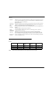
Default Ethernet IP Addresses TABLE 1. Default Product Address for the RVON Product Line Default IP Address Default Subnet Mask RVON-I/O 192.168.0.1 255.255.0.0 RVON-8 192.168.0.2. 255.255.0.0 RVON-1 192.168.0.3 255.255.0.0 RVON-C 192.168.0.4 255.255.0.0 RVON-16 192.168.0.5 255.255.0.0 GPIO-16 192.168.0.6 255.255.0.0 MCII-e 192.168.0.7 255.255.0.0 Cronus 192.168.0.8 255.255.0.0 Zeus III 192.168.0.9 255.255.0.
Power......................................................................................................................................................5W Typical Physical .......................................................................................................................................8.25” W x 6.25” L RVON-C JUMPERS and CONNECTIONS A selectable RS232/485 serial port is at connector J1 Serial (see Figure 2 on page 8) on the backcard.
FIGURE 1.
FIGURE 2. Backcard - RVON-C FIGURE 3.
CHAPTER 2 Installation Installation of the RVON-C Card into the Cronus System When inserting the RVON-C card into the Cronus system, the following considerations need to be made: • Gently insert the RVON-C card into the correct slot. If the card is forced or twisted while inserting, a pin on the backplane could short or break causing the card to become inoperable. • When inserting the RVON-C card into the Cronus system, make sure to insert it into a compatible backcard.
Switches and Connections IMPORTANT: You must remove the card from the frame in order to change any DIP switch settings on the front card, see Figure 1 on page 7). DIP Switches DIP Switch 1 Closed: Configuration via AZedit is disabled Open: (Default) Configuration via AZedit is enabled. Description: DIP Switch 2 Disables configuration changes via AZedit. AZedit will still be able to view the card configuration and connection status.
Configuring the RVON-C Card with AZedit Once the RVON-C card is inserted into the Intercom, AZedit will automatically recognize the card. NOTE: Requires intercom firmware and AZedit software that supports RVON cards. To configure the RVON-C card, do the following: 1. From the Status menu, select I/O Cards. The IO Card Status screen appears showing the types of installed cards. 2. Right -click on an RVON-C card, and select RVON-C Configuration. The RVON-C Configuration screen appears.
3. From the RVON-C drop down list, select the slot in which the RVON-C card resides, if it is not already selected. 4. In the IP Address field, enter the IP Address you have assigned to the RVON-C card. 5. In the Network Mask field, enter the Network Mask of the network to which the RVON-C card is connected. 6. In the Default Gateway field, enter the Default Gateway Address (if applicable) of the network to which the RVONC card is connected.
RVON-C Connection Status Screen The RVON-C connection status screens display information pertaining to RVON-C channel connection. You can only show statistics for one channel on a card at a time. NOTE: To view the RVON-C Connection Status screens make sure both AZedit and the RVON-C card are on the same Ethernet network. The reason this is important is because the statistics are updated once per second. At this rate of dynamic update, a serial port could not pass this much data effectively.
Screen Item Description Select Local Card and Channel RVON Card The card for which you want to view the status. From the RVON drop down list, select the card you want to view. IP Address Displays the IP (Internet Protocol) Address of the card you select. Local Channel One of eight audio channels supported by the RVON-C card. From the Channel drop down list, select the channel for which you want to view the status.
SCREEN ITEM DESCRIPTION Attempts / Drops The number of times a call attempt has been made and dropped. NOTE: The number of attempts should always be one greater than the number of drops. Current Call State The state of the connection. There are two connection states: Connected or Idle. Origination / Termination Displays which end of the connection originated or terminated the call. Local: RVON-C card Remote: device at the other end of the connection.
SCREEN ITEM DESCRIPTION VOIP Playout Statistics Playout Buffer Size Displays how much audio can be received from the network before packets are lost. This is four times bigger than configured packet size. This is a static system setting. Nominal Playout Delay Displays how much audio is collected before playout begins. Playout begins at half the Playout Buffer Size, which is two times the configured packet size. This is a static system setting.
SCREEN ITEM DESCRIPTION Network Statistics Voice Playout Packets (Tx/Rx) Displays the number of voice packets transmitted and received from the other side of the connection. DTMF Relay Packets (Tx/Rx) Displays the number of DTMF (dual tone multiple frequency) relay packets transmitted and received. DTMF relay packets are a bandwidth and quality saving feature within the RVON-C card. Silence Detections Packets (Tx/Rx) Displays the number of times a silence detection packet has been sent or received.
SCREEN ITEM DESCRIPTION Error Counts Invalid Headers Displays how many IP packets could not be parsed. Invalid MAC Address Displays how many invalid MAC addresses tried to connect. Invalid SSRC Displays the number of packets with an invalid SSRC. Invalid Payload Displays how many incorrectly formatted packets were received. DSP to Micro Overrun Displays the number of packets that were lost because the Micro was too busy to receive.
Screen Item Description SERIAL TO ETHERNET The Serial to Ethernet information shows the serial data that is received on the serial connection and transferred to the Ethernet address of the card to which the serial data is sent. Bytes Transferred Displays the number of bytes transferred from the serial connection to Ethernet. Bytes Lost Displays the number of bytes that could not be transferred. Errors Displays the number of errors that occurred during transfer.
View RVON-C Status from Cronus Front Panel Not only are you able to view at the status of the RVON-C from AZedit, but now you can also view the status of your card from the front panel display on the Cronus system. To access RVON-C status from the Cronus front panel, do the following: 1. On the front of the Cronus, tap either of the selector knobs. The top-level menu appears. 2. Turn either selector knob to display Status. 3. Tap the selector knob. The Status sub-menu appears. 4.
TABLE 2. RVON-C status descriptions Action Display When Ethernet is selected: Link Up - Displays whether the Ethernet link is active or inactive. Link Up = Active, Link Down = Inactive Speed - Displays the connection speed in mbps. Can be either 10 mbps or 100 mbps Mode - Displays whether the connection is Half Duplex (data moves in one direction) or Full Duplex (data moves in both directions). Auto-Negotiate - Automatically determines the Ethernet speed and mode, and then adjusts settings accordingly.
Download RVON-C Firmware through AZedit NOTE: 22 AZedit sends the program directly to the RVON-C card over Ethernet. This is different from other I/O cards that receive the firmware from the Master Controller. For this reason, verify the PC running AZedit is on the same network as the RVON-C card. If it is not, AZedit will not be able to find the RVON-C card. To test the connection, ping the RVON-card from a command line. For more information on testing for a connection see Appendix A. 1. Open AZedit.
6. Click Open. The Download Device Firmware window appears. 7. Click Begin Download. The download begins. 8. Click OK. The RVON-C firmware download is complete. This takes a minute or two to occur. 9. Verify the version upgrade in the I/O Card Version Information Window is correct. WARNING: Do NOT reset the Master Controller. Do NOT power down the frame or pull the RVON-C card(s) from the frame until you have verified the new version information from AZedit.
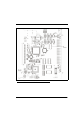
24 J1 SERIAL 4 USB DE-9-P 1 MALE, 9 PINS " D " SUB DE-9-P GPIO J9 1 2 3 2 2 1 GROUND 6 1 J1 " D " SUB CONNECT TO ICP-2000 DE-9-P MALE, 9 PINS N/C J1 CONNECT TO RVON-8 2 6 J8 3 RS485 + J7 4 POWER 2 RS485 - XCP-ADAM-MC J2 CONNECT TO MATRIX MALE, 9 PINS " D " SUB DE-9-P 2 6 XCP-ADAM-MC J2 CONNECT TO MATRIX RS485 - GROUND 17-24 MALE, 9 PINS " D " SUB J2 J6 J4 5 J1 6 J5 7 J3 8 POWER 1 1-8 RS485 + LINE 1 ENC 2 REAR VIEW J2 ETHERNET Digital Matrix Inter
CHAPTER 3 RVON-C Card Serial Port Programming RVON Serial and Telnet Commands RVON card programming can be done via direct serial or telnet connection. There are several physical connections to an RVON board: • Direct serial through custom debug cable (J7 6-pin bottom front) The customer debug cable always functions as the general-purpose debug tool. • Backcard DB-9 J1 The backcard DB-9 (must be disabled/enabled via a DIP Switch because it can also be used for serial port passthrough.
***************************** RVON-C Revision 1.00.02 (C) Copyright 2003 Telex Inc. All Rights Reserved. Flash File System initialized. DIP Switch settings:....XXXX Configuration via AZedit disabled (via DIP Switch 1 on) Back card UART enabled for pass-through serial (via DIP Switch 6 off) Boot downloader disabled (via DIP Switch 7 off) Autoload enabled (via DIP Switch 8 off) Monitor Revision 1.00.
Creating RVON application... -> Bringing DSP subsystem out of reset...
Access Serial Command Mode There are many different serial port commands supported from here but it is NOT recommended that any be used EXCEPT: dbgcmd 1. Type “dbgcmd”, then press Return. This places the serial port into the MXP> (MXP command mode) The MXP Command Mode is the only mode that will be used. The table below is a list of commands supported from the MXP Shell Prompt.
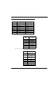
Serial Command Table TABLE 3. Serial Command Table Command Variable 1 Variable 2 set rvon Description Help screen which lists all “set rvon” commands. set rvon ip_addr X.X.X.X Set the IP Address for the RVON Card. set rvon netmask X.X.X.X Set network mask for the RVON Card. set rvon gateway X.X.X.X Set the gateway IP Address for the RVON-8 card. set rvon user abcdefg Set the RVON user name for telnet access.
TABLE 3. Serial Command Command Table Variable 1 Variable 2 Description show channel [chan] Display current settings show emac Display current settings RVON-C Default Setup Every attempt is made to ensure the board is shipped from the factory containing the following: All are “set rvon” commands VARIABLE ENVIRONMENT NAME DEFAULT VALUE DESCRIPTION ip_addr EMACA_IPADDR x.x.x.x IP Address for the RVON-C Card netmask EMACA_NETMASK 255.255.255.
CHAPTER 4 RVON-C Quick Start This guide explains briefly how to install and configure an RVON-C card in a Cronus system. It contains the following sections: 1. Install the Front card and the Back card into Cronus 2. Connect Ethernet 3. Connect to Cronus frame in AZedit 4. Configure the RVON-C card 5. Configure the devices the card will connect with. 6. Begin Operation.
Launch AZedit and Connect to the Cronus Frame NOTE: You can connect to Cronus using a Serial, USB or Network Connection. The following instructions show how to connect using a Network connection. For more information on configuring the network connection for the Cronus, see the Cronus User Manual (9350-7770-000). To connect to the Cronus system from AZedit, do the following: 32 1. From the Options menu, select Communications. The Communications screen appears. 2. Verify that Network is selected. 3.
4. Highlight Cronus in the Intercoms window and click OK. 5. Click OK when the Configuration Change message appears. 6. You will now see CRON in the lower right hand corner of the AZedit application.
Configure the RVON-C Card Once you have a connection to Cronus, you are now ready to configure the RVON-C card within the Cronus system. To configure the RVON-C Card, do the following: 1. From the Navigation bar at the bottom of the AZedit application, click the RVON button. The RVON Configuration screen appears. 2. From the RVON-C drop down list, select the slot in which the RVON-C card resides, if it is not already selected. 3.
10. From the Device Type drop down list, select the type of device to which the RVON-C card is connecting. 11. From the Device Channel drop down list, select the channel on the device to which the RVON-C card will communicate. 12. From the CODEC Type drop down list, select the CODEC type you want to use for this channel. 13. From the Packet Size drop down list, select the size of each audio packet. NOTE: 14. NOTE: A CODEC is an algorithm used to compress audio.
36 • • For RS232, jumper pins 2 & 3 of J10, J11, and J12 3. Once you have set the correct configuration, replace the RVON-C into Cronus and hook the DB-9 connector to the RVON-C backcard. 4. Use Table 3, “Serial Command Table,” on page 29 to configure your RVON-C card.
APPENDIX A Basic Network Configuration Basic Network Configuration This section covers basic network configuration set-up and testing. Also covered are basic concepts and operations, including the difference between LAN and WAN networks and how IP Addressing is used. In a networked environment, such as a company, typically there are many computers connected together using a router or a switch. In larger companies, there may be several different routers distributed in buildings and plant locations.
FIGURE 5. Local Area Network Diagram WIDE AREA NETWORK A wide area network (WAN) connects two or more LANs and can span a relatively large geographical area. For example, Telex Headquarters in Burnsville, MN is connected to several branch offices in Nebraska and Arkansas over a WAN. The largest WAN in existence is the Internet. FIGURE 6.
ACCESSING THE WIDE AREA NETWORK (WAN) Figure 3 shows LAN IP Addresses using a common IP Address, 10.2.100.X (192.168.X.X is another common address). Most devices are shipped with these addresses as its default. It is recommended to use these addresses for LANs. FIGURE 7. Network Address Translation NETWORK ADDRESS TRANSLATION (NAT) Using the initial IP Address, then converting it to a valid WAN IP Address is how the network address translation works, in theory.
TABLE 5. Packet Translation Packet before Translation Source Packet After Translation Destination Source IP Address Port Number IP Address Port Number IP Address Port Number IP Address Port Number To Internet 10.2.100.1 1031 192.156.136.22 80 99.5.1.30 1032 192.156.136.22 80 From Internet 192.156.136.22 80 99.5.1.30 1032 192.156.136.22 80 10.2.100.
IP ADDRESSES If you do not know your IP Address, you can open a DOS screen in a Windows®- based environment and bring up the ipconfig screen. To find your IP Address using ipconfig, do the following: 1. From the Start Menu, open a Command Prompt screen. 2. At the prompt, type ipconfig, then press Enter. The IP configurations appear for your machine, such as the DNS suffix, IP Address, Subnet Mask, and Default Gateway. 3. At the prompt, type Exit to close the screen.
Ping a Computer Pinging a computer on the network makes sure it is able to be “seen” and receive messages on the network. NOTE: You can also ping your RVON-8 card to verify that it is responding over the network by putting the cards IP Address in place of the computer IP Address. To Ping a computer on the network, do the following: 1. 2. From the Start menu, select Run.... At the Run command, type CMD to open a Command Prompt screen. 3.
2. At the prompt, type tracert and type the url or IP Address you want to trace. 3. Press Enter. The details of the tracer route are displayed. NOTE: 4. You will the message “request timed out” if the IP Address/ port IN or OUT is denied to the incoming or outgoing message. When you are finished, type exit to close the Command Prompt screen. RVON Configuration RVON cards use ports for communication of audio and control packets.
Below, is an example of a router configuration screen. Not all routers are configured the same way and may not look exactly like this screen. NOTE: 44 Linksys™ supports up to 253 nodes on a router. This is why it is called a Router/Switch because there are WAN functions like a router as well as having a 4-port LAN switch. It also does not support simultaneous forward and DHCP.
Network Terminology Bridge A bridge is a device that connects two LANs, or two segments of the same LAN that use the same protocol. Sometimes called “transparent bridges” they work at the OSI model layer 2. Simply put, they are not concerned with protocols. Their main job is to pass data to a destination address that is predetermined in the data packet. With a bridge, all of your computers are on the same network subnet (see Subnet).
46 LAN A LAN is a computer network that connects a relatively small area (a single building or group of buildings). Most LANs connect work stations and computers to each other. Each computer (also known as a “node”) has its own processing unit and executes its own programs; however, it can also access data and devices anywhere on the LAN. This means that many users can access and share the same information and devices. A good example of a LAN device is a network printer.
47
APPENDIX A RVON Trunking Connections In this chapter you will find the following drawings: • • • • • AZedit Via RVON-8 RS-232 Mode CS9500 Trunking Via RVON-I/O To RVON-8 ADAM Trunking Via RVON-8 Zeus II Trunking Via RVON-I/O To RVON-C Cronus Trunking Via RVON-I/O To RVON-8 49
50
Figure 8: AZedit Via RVON-8 RS-232 Mode 51
Figure 9: CS9500 Trunking Via RVON-I/O To RVON-8 52
Figure 10: ADAM Trunking Via RVON-8 53
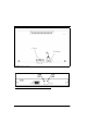
Figure 11: Zeus II Trunking Via RVON-I/O to RVON-C 54
Figure 12: Cronus Trunking Via RVON-I/O To RVON-8 55
Figure 13: RVON-16 Trunking 56
Notes 57