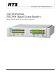
User Instructions DSI 2008 Digital System Interface ADAM, ADAM-M, ADAM CS, Zeus, and Zeus III Intercoms F.01U.193.295 Rev.
ii DSI-2008 PROPRIETARY NOTICE The product information and design disclosed herein were originated by and are the property of Bosch Security Systems, Inc. Bosch reserves all patent, proprietary design, manufacturing, reproduction, use and sales rights thereto, and to any article disclosed therein, except to the extent rights are expressly granted to others. COPYRIGHT NOTICE Copyright 2012 by Bosch Security Systems, Inc. All rights reserved.
DSI-2008 iii Important Safety Instructions 1. Read these instructions. 2. Keep these instructions. 3. Heed all warnings. 4. Follow all instructions. 5. Do not use this apparatus near water. 6. Clean only with dry cloth. 7. Do not block any ventilation openings. Install in accordance with the manufacturer’s instructions. 8. Do not install near any heat sources such as radiators, heat registers, stoves, or other apparatus (including amplifiers) that produce heat. 9.
iv Bosch Security Systems, Inc. DSI-2008 User Manual F.01U.193.295 Rev.
Table of Contents DESCRIPTION AND SPECIFICATIONS ................................................................................. 3 General Description .................................................................................................................................3 Features ....................................................................................................................................................3 Front and Back Panel Descriptions ...................................
2 Bosch Security Systems, Inc. DSI-2008 User Manual F.01U.193.295 Rev.
CHAPTER 1 Description and Specifications General Description The DSI 2008 Dual Digital Hybrid interfaces two (2), 2-wire intercom lines to two(2), 4-wire intercom lines. Unlike earlier analog hybrids, the DSI 2008 features advanced digital signal processing to achieve automatic nulling of the 2-wire lines. Plus, each hybrid features convenient peak-reading level meters to quickly match the levels between the lines being interfaced. The result is easy and accurate setup.
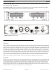
4 Description and Specifications DSI-2008 Half-rack Wide, 1RU High: Two DSI 2008s fit into a single rack space. Compatible with RTS TW rack mount hardware. Can be mixed with other TW equipment. Universal Power Pack: Ready for worldwide use. Automatically accepts any main voltage from 100-250 VAC, 50/60Hz. Power pack equipped with locking DIN connector for attachment to the DSI 2008. FIGURE 1.
DSI-2008 Description and Specifications 5 Specifications 2-Wire Ports Input / Output Impedance 5,000, nominal Operating Level Audiocom: 1 VRMS, nominal RTSTW: 775 mVRMS, nominal 4-Wire Ports Input Impedance 10k , nominal Output Impedance 200 Operating Levels -10dBu, 0dBu, +4dBu, +8dBu, +12dBu System to System Frequency Response 200Hz to 3.
6 Description and Specifications Bosch Security Systems, Inc. DSI-2008 User Manual F.01U.193.295 Rev.
CHAPTER 2 Installation Mounting Place the DSI 2008 on a desktop, or install it in an equipment rack using an RTS MCP Rack Mount Kit. Several rack mount options are available. There are no special ventilation requirements for the DSI 2008, but allow for ventilation around the power pack. • NOTE: If the DSI 2008 has the call signal option, the power indicator flashes whenever a call signal is received from either 2-wire line, and activity on the level display helps to indicate which line is calling.
8 Installation DSI-2008 Audio Connections for the Other 4-wire Communications Systems To connect to other 4-wire communication systems, do the following: 1. Construct 9-pin or RJ-11 cables to connect from the 4-wire system to the DSI 2008. To connect to the System A hybrid, use either J2A or J3A; for the System B hybrid, use either J2B or J3B.
DSI-2008 Installation 9 . FIGURE 2. Rack Mount Configurations Bosch Security Systems, Inc. User Manual F.01U.193.295 Rev.
10 Installation DSI-2008 2-Wire Audio Connections RTS TW Audio Connections To configure 2-wire connections, do the following: 1. Use standard TW intercom cables. Standard TW system cables can carry either one (1) or two (2) channels. Each hybrid in the DSI 2008 can only interface one (1) TW channel to one (1) 4-wire channel, the channel is determined by the front panel 2W CHAN SEL switch.
DSI-2008 Installation 11 FIGURE 3. Using a JB-2 Junction Box to split a 2-channel Audiocom cable into two 1-channel cables. Other 2-wire Audio Connection 1. Use the J1A connector on the back of the DSI 2008 to connect one 2-wire line to the System A hybrid. Use the J1B connector to connect a second 2-wire line to the System B hybrid.
12 Installation DSI-2008 NOTE: If System A or System B will not be used, set the 2W CHAN SEL switch to the off position and attach a dummy load to the TW XLR connector. 4-Wire Call Signal Connections NOTE: These connections require the call signal option. Call Signal Connection for ADAM, ADAM-M, ADAM CS, Zeus and Zeus III You can use the General Purpose Interface (GPI) connector to interface call signals. The pin-out of the connector is the same for all of these intercom systems Table 1 on page 13.
DSI-2008 Installation 13 This example uses GPI outputs #1 and #2 and GPI Input #1; however, you may use any other available GPI inputs and outputs. The Call Enable/Inhibit connection is optional. It gives you the ability to disable call signalling using a GPI output. Pin No.
14 Installation TABLE 2.
DSI-2008 Installation 15 GPI OUTPUT NUMBERSa RELAY CONTACT PIN NUMBERS UIO-256 FRAME #1 UIO-256 FRAME #2 UIO-256 FRAME #3 UIO-256 FRAME #4 NORMAL CLOSED (NC) CONTACT COMMON CONTACT NORMAL OPEN (NO) CONTACT 1 17 33 49 38 13 40 2 18 34 50 39 14 15 3 19 35 51 41 16 43 4 20 36 52 42 17 18 5 21 37 53 44 19 46 6 22 38 51 45 20 21 7 23 39 55 41 22 49 8 24 40 56 48 23 24 9 25 41 57 26 1 28 10 26 42 58 27 2 3 11 27 43 59 29 4 31
16 Installation DSI-2008 4-Wire Call Receive The DSI 2008 receives call signals from the 2-wire system, then converts this to relay contact closure for use as a 4-wire call receive indication. The DSI 2008 also provides +5 VDC which can be connected to the relay contacts to generate a DC output signal instead of a contact closure. Connections for a simple contact are shown in Figure 6 on page 16. FIGURE 6. III.
DSI-2008 Installation 17 2-Wire Call Signal Call Signal Connections for Audiocom and RTS TW The call signals are superimposed on the audio signal, so no separate call signal connections are required.
18 Installation Bosch Security Systems, Inc. DSI-2008 User Manual F.01U.193.295 Rev.
CHAPTER 3 Operation Setup Instructions 1. Attach the power pack to the DSI 2008. 2. Apply power to all components. 3. Confirm the power indicator is lit on the DSI 2008 front panel. NOTE: The power indicator flashes when a call signal is received from a 2-wire line, if the call signal option board is attached. The DSI 2008 level displays should help to confirm which line is calling. 4. Use the level adjust trimmers to fine tune the listen levels.
20 Operation DSI-2008 Operating Notes for ADAM, ADAM-M ADAM CS Zeus and Zeus III Intercom Systems 1. In AZedit use port alpha setup to name each 4-wire intercom port that is connected to the DSI 2008. Choose names which help indicate which 2-wire line is being interfaced. 2. Key assignment, party line assignment, etc. is the same as for any other intercom port. 3.
APPENDIX A Access and Configuration Internal Access 1. Remove six screws from the back cover. 2. Remove the top cover. This provides access to all internal adjustments. 3. For option card installation, slide the circuit board out toward the back to remove it from the bottom cover. AUX Telex Communications, Inc., Made in U.S.A. AUX J5 POWER +5V 3A +15V 1.6A -15V 0.3A J4A J4B RTN +5V J3B J2B 4 WIRE SYSTEM Bosch Security Systems, Inc.
22 DSI-2008 Mode Dip Switch Settings S301 controls the operating mode for System B and S302 controls the operating mode for System A. Settings are summarized as follows: TABLE 3. Mode DIP Switch Settings Switch Settings Description 1 2 3 4 Open Open Open Open Configuration 1, Full-Duplex Mode (Default) Closed Open Open Open Configuration 2, Half-Duplex Mode Open Open Open Closed Tone Test Mode Full-Duplex Definition: Both sides of the line can talk simultaneously.
DSI-2008 23 Notes Bosch Security Systems, Inc. User Manual F.01U.193.295 Rev.
Bosch Security Systems, Inc. 12000 Portland Avenue South Burnsville, MN 55337 U.S.A. www.boschcommunications.