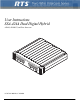
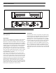
User Instructions SSA-424A Dual Digital Hybrid ADAM, ADAM CS, and Zeus Intercoms LE V SE EL T -15 PO WE R -12 -9 -10 dB 0dB +1 2d +4 B d B +8 4W dB RE LE F S VE EL L SY ST EM -6 A -3 0 +3 2 +6 1 BA L TW +9 CH AN 1 T O +1 4W 2 SE L 2 BA TO 2W LE V SE EL T L -15 -12 -10 dB 2d B +1 0d SY ST EM -9 -6 B -3 B 0 +3 +4 dB +8 4W dB RE LEV F S EL EL 1 2 BA L +6 TW +9 CH AN 1 T O +1 4W 2 SE TO 2W L 2 BA TM L SS A- 9350-7824-000 Rev C 10/2008 42 4A
PROPRIETARY NOTICE SHIPPING TO THE MANUFACTURER The product information and design disclosed herein were originated by and are the property of Telex Communications, Inc. Telex reserves all patent, proprietary design, manufacturing, reproduction, use and sales rights thereto, and to any article disclosed therein, except to the extent rights are expressly granted to others. All shipments of product should be made via UPS Ground, prepaid (you may request from Factory Service a different shipment method).
Table of Contents CHAPTER 1 Description and Specifications ....................1 General Description ...........1 General Features ...............1 Front and Back Panel Descriptions ............2 Front Panel ....................2 Back Panel .....................2 Specifications ..............................................3 CHAPTER 2 Installation ...................................................5 Mounting ......................................................5 4-Wire Audio Connections ...............
2
CHAPTER 1 Description and Specifications General Description The SSA-424A Dual Digital Hybrid interfaces two, 2-wire intercom lines to two, 4-wire intercom lines. Unlike earlier analog hybrids, the SSA-424A features advanced digital signal processing to achieve automatic nulling of the 2-wire lines. Plus, each hybrid features convenient peak-reading level meters to quickly match the levels between the lines that are being interfaced. The result is easy and accurate setup.
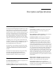
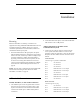
Description and Specifications LEVEL SET LEVEL SET SYSTEM A TO 4W -15 -12 -9 -6 0 -3 +3 +6 +9 +12 SYSTEM B TO 4W -15 -12 -9 -6 0 -3 +3 +6 +9 +12 TO 2W +4dB 0dB -10dB 2 +8dB +12dB 1 OFF BAL OFF 1 POWER TO 2W +4dB 2W CHAN SEL 2 0dB -10dB 1 OFF BAL OFF 2W CHAN SEL 1 BAL 4W LEVEL REF SEL AUX 2 +8dB +12dB 4W LEVEL REF SEL Telex Communications, Inc., Made in U.S.A. 2 TM AUX BAL SSA-424A J5 POWER +5V 3A +15V 1.6A -15V 0.
Specifications Specifications 2-Wire Ports Input / Output Impedance 5,000 ohms, nominal Operating Level Audiocom: 1 VRMS, nominal RTSTW/ClearCom: 775 mVRMS, nominal 4-Wire Ports Input Impedance 10k ohms, nominal Output Impedance 200 ohms Operating Levels -10 dBu, 0 dBu, +4 dBu, +8 dBu, +12 dBu System to System Frequency Response 200 Hz to 3.
Description and Specifications 4
CHAPTER 2 Installation On the SSA-424A front panel, set the 4W LEVEL REF SEL switches to the +8 dB position. Mounting 2. Place the SSA-424A on a desktop, or install it in an equipment rack using an RTS MCP Rack Mount Kit. Several rack mount options are available. There are no special ventilation requirements for the SSA-424A, but allow for ventilation around the power pack.
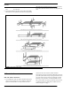
Installation 2. Pin 5 Balanced Audio - 4-wire input Pin 6 No Connection On the SSA-424A front panel, set the 4W LEVEL REF SEL switches to the position which most closely matches the audio input and output levels of your 4-wire system. If you don’t know the levels, select the +8 dB position for now. FIGURE 2. Rack Mount Configurations 2-Wire Audio Connections RTS TW Audio Connections 1. 6 Use standard TW intercom cables.
2-Wire Audio Connections NOTE: The SSA-424A features internal DC isolation. You can therefore connect to the SSA-424A to powered TW cables, and it will not draw any power from the TW system. On the SSA-424A front panel: For System A and System B, set the 2W CHAN SEL switch to the appropriate position. To interface to TW channel 1 select position 1; for TW channel 2, select position 2.
Installation NOTE: TW systems must provide termination on the audio channel.
4-Wire Call Signal Connections FIGURE 5. Call signal connections for ADAM, ADAM CS, and Zeus Intercom Systems. This example uses GPI outputs #1 and #2 and GPI Input #1; however, you may use any other available GPI inputs and outputs. The Call Enable/Inhibit connection is optional. It gives you the ability to disable call signalling using a GPI output. However, when connecting to a Clear-Com intercom system, if an enable/inhibit switch is not connected, a jumper must be installed for any other application.
Installation TABLE 2.
4-Wire Call Signal Connections TABLE 3. UIO-256 GPI Outputs Connector (J5) GPI OUTPUT NUMBERSa RELAY CONTACT PIN NUMBERS UIO-256 FRAME #1 UIO-256 FRAME #2 UIO-256 FRAME #3 UIO-256 FRAME #4 NORMAL CLOSED (NC) CONTACT COMMON CONTACT NORMAL OPEN (NO) CONTACT 15 31 47 63 35 10 37 16 32 48 64 36 11 12 a. Dependent on UIO-256 DIP Switch SW1 Settings for Input/Output Range as summarized in the UIO-256 manual.
Installation 2-Wire Call Signal Call Signal Connections for Audiocom, RTS TW and Clear-Com The call signals are superimposed on the audio signal, so no separate call signal connections are required. However, make sure that a call enable switch or jumper is installed for Clear-Com applications as shown in Figure 6 on page 11 and Figure 7.
CHAPTER 3 Operation General Instructions 1. Attach the power pack to the SSA-424A and apply power to all components. Confirm the power indicator is lit on the SSA-424A front panel. NOTE: The power indicator flashes when a call signal is received from a 2-wire line, if the call signal option board is attached. The SSA-424A level displays should help to confirm which line is calling. 2. Use the level adjust trimmers (Figure 8) to fine tune the listen levels.
Operation Optional call signal input using the GPI 4. • In AZedit, click GPI In on the toolbar. This opens the GPI Setup screen. • Whichever GPI Input you are using for 4-wire call receive, select that GPI Input from the list (doubleclick). This will open the Edit GPI Input window. • In the Port Alpha list box, select the intercom port that is named in step 1. • In the Key Number box, type 1. This selects key 1 at the intercom you specified in the previous step. • Select Talk Key. • Click Done.
Appendix A Internal Access Mode Dip Switch Settings 1. Remove six screws from the back cover. S301 controls the operating mode for System B and S302 controls the operating mode for System A. 2. Remove the top cover. This provides access to all internal adjustments. 3. For option card installation, slide the circuit board out toward the back to remove it from the bottom cover. Settings are summarized as follows: TABLE 1. Mode AUX Telex Communications, Inc., Made in U.S.A.
Call Signal Option Card Installation Use these instructions to install a Call Signal Option Card in a SSA-424A that was originally ordered without it. 1. Disassemble the SSA-424A as previously described. 2. Assemble the standoffs to the circuit board using the supplied screws and lock-washers. 3. Connect the supplied power cable from J8 on the option card to J303 on the main board of the SSA-424A. 4. Insert the connectors on the option card into the connectors on the main board. 5.