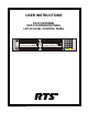
USER INSTRUCTIONS KP-32 KEYPANEL EKP-32 EXPANSION PANEL LCP-32 LEVEL CONTROL PANEL Listen Headset MENU Talk Vol. Sel. FWD Mic .3 2.3 $1'< .3 '$1 .3 7,) .3 ™ KP-32 1 2 3 9350-7656-000 Rev A, 12/99 PL AU TO 2 3 IFB ISO PR EFIX 4 5 RE LAY TY PE CO PY C W E-PN L 7 8 EX COP Y DI SPLAY MUTE CLR Call waiting Listen 5 BACK 1 6 9 MU LT Headset 4 :.3 :.3 ) '$1 .3 .3 6/ .
PROPRIETARY NOTICE CUSTOMER SUPPORT The RTS product information and design disclosed herein were originated by and are the property of Telex Communications, Inc. Telex reserves all patent, proprietary design, manufacturing, reproduction, use and sales rights thereto, and to any article disclosed therein, except to the extent rights are expressly granted to others. Technical questions should be directed to: Customer Service Department RTS/Telex, 2550 Hollywood Way, Suite 207 Burbank, CA 91505 U.S.A.
End-User License Agreement for Telex® Software IMPORTANT - Please read this document carefully before using this product. THIS DOCUMENT STATES THE TERMS AND CONDITIONS UPON WHICH TELEX COMMUNICATIONS, INC. (the “COMPANY”) OFFERS TO LICENSE THE INSTALLED SOFTWARE OR PROGRAM (“the SOFTWARE”) FOR USE WITH THE PRODUCT IN WHICH IT WAS INSTALLED. YOU ARE AGREEING TO BECOME BOUND BY THE TERMS OF THIS AGREEMENT. IF YOU DO NOT AGREE TO THE TERMS OF THIS AGREEMENT, DO NOT USE THIS PRODUCT.
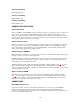
TABLE OF CONTENTS DESCRIPTION AND SPECIFICATIONS ............................................................. 6 DESCRIPTION.................................................................................................................... 6 FEATURES......................................................................................................................... 6 OPTIONS............................................................................................................................
GLOSSARY ....................................................................................................... 46 INDEX................................................................................................................. 52 KP9X KEYPAD SEQUENCE QUICK REFERENCE.......................................... 55 KP9X DISPLAY SEQUENCES .......................................................................................... 55 KP9X SETUP PAGE ASSIGNMENT ................................................
DESCRIPTION AND SPECIFICATIONS DESCRIPTION TM The RTS Model KP-32 Keypanel fits in a standard 19" rack and is 2 rack spaces high. It has 32 lever keys: 30 keys are for intercom talk/listen assignment; 1 key is for call waiting response; and 1 key is for headset/microphone/program selection and volume setup. The KP-32 combines all of the programmable features of the KP9X Series Keypanels and the KP-12 Keypanel.
SPECIFICATIONS Microphone Preamplifier Audio Input Level (at 1 kHz): Electret Mic: -42 dB, 150 ohms Dynamic Mic: -60 dBm, 150 ohms Output Level (to matrix): +8 dBu, ± 0.
Headset Connector Connector Type XLR5 female Pin-out Pin 1: Mic low Pin 2: Mic high Pin 3: Common Pin 4: Headphone left high Pin 5: Headphone right high Power Input Connector Type: 5-pin locking DIN Pin-out Pin1: Common Pin2: Common Pin3: +5VDC, 1.50A Max. Pin4: -15VDC, 0.150A Max. Pin5: +15VDC, 0.5A Max.
INSTALLATION OPTION DIP SWITCH SETTINGS Switch 1: Latch Enable/Disable Default setting = Open: Enable. Description: An intercom key can always be turned on for momentary conversation by pressing and holding the key during the conversation. There is also an electronic latching feature that lets you tap intercom keys to turn them on or off. This permits convenient hands-free conversation. However it can also result in a talk circuit being left on unintentionally.
Switch 6: Not Defined Default Setting: Open. Switch 7: Test/Debug Default Setting: Open. Switch 8: Test/Debug Default Setting: Open. ADDRESS SWITCH SETTING General Information In Zeus, ADAM CS, and ADAM Intercom Systems, intercom ports are arranged in groups of 8. All ports in a group share a common data port. Each KP-32 keypanel is uniquely identified on the data port by the setting of its Address switch. The method of determining the proper Address switch setting varies for each intercom system.
Each LCP-32 adjusts the listen levels for 16 keypanel keys, and you can connect as many LCP-32 panels as required to adjust all keys on the KP-32 and on an optional EKP-32 Expansion Panel. An interconnect cable is supplied with each LCP-32. Connect the first LCP-32 to the LCP connector on the KP-32. Connect the second LCP-32 to the first LCP-32, and so forth. Note, when arranging LCP-32 panels in an equipment rack, you should put them directly above or below the keys they will be used to adjust.
Power Supply Connector Align and insert the external power supply connector. Tighten the locking ring. Connect a power cord to the power supply and to an AC power source. The power supply accepts 100-240 VAC, 50/60 Hz. At power-up, the alphanumeric displays will first show asterisks (****). After a few moments the intercom key assignments will display. If the keypanel cannot establish communication with the intercom system, all alphanumeric displays will continue to show asterisks.
BASIC KP-32 OPERATION SCREEN SAVER OPERATION If the KP-32 is set for screen saver operation, the alphanumeric display automatically shuts off after several minutes of inactivity. The display reactivates on incoming call or when the keypanel operator actuates any control. ☞ Switch 3: Screen Saver Enable / Disable, page 9. ☞ You can override the normal timeout period for screen saver operation and immediately place the keypanel in screen saver mode. See "Service Menu, Disply Dim", page 37.
Continuous Red Talk LED ("In-use"): The key is off, but someone is talking to the destination. This indication is provided for any local PL, IFB, ISO, or TIF key. It does not apply to remote IFB or ISO keys. This indication is provided so keypanels operators know when critical director communications are occurring.
For latching operation (if enabled) tap a key; it will turn on and remain on. Tap the key again to turn it off when finished. ☞ Latching may be turned off for the entire keypanel by setting DIP switch 1 on the KP-32 back panel to the Closed position. Latching may be disabled for individual keys on a keypanel using ADAMedit: Click the KP button on the ADAMedit toolbar to open the Keypanels / Ports setup screen. Select the intercom port where the keypanel is connected.
☞ Solo key setup / display: "Key Option Menu, Solo", page 36. Operation of Intercom Talk Keys with the Speaker DIM Setting Activating any talk key will cause the speaker or headphone volume at this keypanel to diminish by the amount specified in the Dim menu item on the Service menu. Note: do not confuse this with the Talk+DIM auto function previously described (page 15). Talk+DIM affects the speaker or headphones on other keypanels when a particular talk key is activated on this keypanel.
TELEPHONE OPERATION ☞ Note: Telephone operations require an optional TIF-951 Telephone Interface. Also, you must first assign an intercom key to talk/listen to the TIF. We recommend a talk+auto listen assignment. RECEIVING A PHONE CALL When there is an incoming telephone call, the talk LED will flash red next to the KP-32 key that is assigned to the TIF. Activate the key to answer the call. ☞ The red flash for incoming TIF call is the default operation.
c. Tap the TIF talk key. The TIF key talk and listen indicators will turn off and the TIF-951 "OFF" LED will activate. The TIF-951 is now ready for another call. KP9X Redial Sequence ☞ The last dialed phone number is always stored at the TIF and over-writes any previously dialed phone number. If several people have access to the TIF, redial may not produce the results that you expect! 1. Tap the PHONE key to activate dialing mode. 2. Tap "up" on the TIF key to activate listen. 3. Tap CLR 0 4.
5. Hang up using theKP9X hang-up sequence, page 17. DIALING AND HANGING UP USING THE KP-32 DIALING MENU The dialing menu will only activate when talking to an intercom port that has the "Port is TIF" check box activated in ADAMedit. (In ADAMedit, click the "KP" button to access the Keypanels / Ports screen, then select the port where the TIF-951 is connected, then click the "Edit" button, then click the "Advanced" tab. Place a check mark next to "Port is TIF".
☞ Note: Occasionally, you may receive intercom an intercom caller name in the Call waiting window while you are talking on the phone. In this case, the dialing menu options will be cleared from the Call waiting window, and the +CPI WR option won't be available. Instead of trying to reenter the menu system, use the "KP9X Keypad Hang-up Sequence", page 17. Autodial ☞ Autodial is only available after you have saved autodial numbers. See "Key Option Menu, Auto Dial", page 34. 1. Turn on the TIF talk key.
KP9X SERIES KEYPAD PROGRAMMING ☞ A summary of the keypad programming sequences is located at the back of the manual for quick reference. KEYPAD PROGRAMMING, DISPLAY REQUESTS Display requests let you view information about the keypanel configuration. You can display information by two methods: either by entering sequences on the programming keypad, or by scrolling the names of display requests in the Call waiting window and then selecting the desired display request.
Since the KP-32 requires 2 setup pages, it uses the main page assignments and also one expansion page (Figure 3). The EKP-32 uses two additional expansion pages. Expansion 1 (X1) L ist en H ea d se t M E N U Vo l. Se l. Ta lk .3 2. 3 $1'< .3 '$1 .3 7 ,) .
Display Requests Using Scrolling The display requests described previously can also be accessed using scrolling. Scrolling also offers several additional features. To use scrolling, tap FUNC DISPLAY followed by ↓↓ or ↑↑ to scroll through the list of display requests. The display request names will appear in the Call waiting window as follows: ,F PGM: Displays the calculated port number. CLR to quit. /GX PGM: Displays level 2 talk assignments. CLR to quit. /UVP PGM: Displays listen assignments.
☞ To display setup page assignments at any time, see "Display Setup Page Assignments", 21. KEYPAD PROGRAMMING, ASSIGNING INTERCOM KEYS General There are three methods to assign intercom keys with keypad programming. These methods are summarized below and explained on the following pages. • Key Assignment using Keypad Numeric Entry: Using this method, you enter the panel number, party line number etc. that you wish to assign to a key.
5 All call (talk level 1 only) 6 DIM (talk level 2 only, for point-to-point key, must enter 00 first) 7 Auto table (listen only, when talk level 1 is an IFB assignment) 4. Trunked intercoms only: (Skip when assigning auto functions or local key assignments.) Select an intercom matrix (tap 1 , or 2 etc.). ☞ Intercom system numbers are the numbers that appear in the “Icm” column in CStrunk when you select “Names” or “Setup” from the Intercoms menu. 5. (Skip when assigning auto functions.
4. Press the talk or listen key to which you wish to copy. The name of the key assignment should appear in the display above the key. ☞ If a key will not accept an assignment, the destination that you are trying to assign may not have scrolling enabled in ADAMedit. Or, the key that you are trying to assign may be restricted in ADAMedit. Programming Key Assignments Using Alpha Scrolling Alpha scrolling lets you scroll through a list of names of ports, party lines etc. in the Call waiting window.
6. In single-step mode, use the ↑↑ ↓↓ keys to make your final intercom port selection. ☞ If you cannot locate the destination that you are looking for, it may not have scrolling enabled in ADAMedit. 7. Copy the selected port to a talk or listen key: a. Tap COPY b. Tap down on an intercom key to assign talk, or tap up to assign listen. Clearing a Key Assignment There are two ways to clear a key assignment: Method 1: Clearing the Call waiting Window and Copying it to a Key 1.
THE KP-32 MENU SYSTEM ☞ A chart of the menu system is located at the back of the manual for quick reference. MENU SYSTEM, MENU ACCESS 1. Clear all names from the Call waiting display (if not clear) by tapping "up" one or more times on the Call waiting key. 2. Tap MENU to activate the menu system. 3. Press ↓↓ to scroll forward through the list of menus. Press ↑ ↑ to scroll back. 4. Tap FWD or PGM to enter a menu. Tap BACK to exit a menu. 5. Within a menu: • Press ↓↓ or ↑ ↑ to scroll.
keypanel. In this case, use the ↓↓ and ↑ ↑ keys to scroll through the list of names. You can then press the Call waiting key to ask the person at the other end to turn off their talk key. Display Menu, Key Groups Use the ↓↓ or ↑ ↑ key to select Group 1, Group 2, etc. Then press FWD or PGM to display the group. The talk and listen LEDs of the master key will be lit red and the talk and listen LEDs for the slave keys will be lit green. ☞ Key Groups setup: Key Option Menu, Key Groups, page 35.
2. Tap Menu 3. Tap ↓↓ to scroll down to the .G[ $UUKIP menu. 3. Tap PGM or FWD to enter the menu. ☞ If you do not have a trunking intercom system, skip to step 5. 4. 5. Remote key assignment only (trunking systems only): If your intercom system is configured for trunking, 0CVTKZ displays in the Call waiting window. You must select a remote intercom matrix before assigning intercom keys to destinations in that matrix.
8. Tap PGM or FWD to select the assignment. 9. 7CNM /XN should now display in the Call waiting window. Press ↓↓ or ↑↑ if necessary to select a different option. Options are as follows: • Talk Lvl 1: Assigns only talk level 1. Leaves the listen assignment as is. • Listen: Assigns only listen. Leaves the talk assignment as is. • Talk + AF: Assigns talk level 1, with auto-follow listen. • Talk + AL: Assigns talk level 1, with auto-listen. • Talk + AM: Assigns talk level 1, with auto-mute listen.
Key Assign Menu, Pt-to-Pt Assigns a key that talks or listens to another intercom port. Note that some pt-to-pt destinations may be non-keypanel devices that cannot activate talk and listen paths. Therefore, if you want full communication, you may need to assign both talk and listen on the key. Key Assign Menu, Party Line Assigns a key that talks and/or listens to a party line. The key will have no effect until members have been assigned to the party line in ADAMedit.
• AutoFollow (AF, for listen keys only) • Auto Listn (AL, for listen keys only) • Auto Mute (AM, for listen keys only) • Auto Recip (AR, for listen keys only) • All Call (AC, for talk level 1 only) • Dim ( Dim Table function, for talk level 2 on point-to-point keys only) 2. Press FWD or PGM to select the desired auto function. 3. 7CR .G[ displays. Tap an intercom key to assign the selected auto function. Tap up to assign all auto functions except All Call or DIM. Tap down for All Call or DIM.
1. Press FWD or PGM to select 5GUGV 9QNU in the Key Assign menu. 2. 'QPG displays. All key gains are now reset to the default level. 3. Tap CLR to quit. ☞ You do not need to run Save Cfg after resetting key gains. These settings are stored in the intercom system. Key Assign Menu, Setup Page Use this menu item to change the setup page assignments on the KP-32 or EKP-32. One setup page is used for the top row of keys, and another setup page is used for the bottom row. 1.
5. $ 'KCN displays (store auto dial number 1). To store a different auto dial number, press ↓↓ or 6. Tap PGM. 7. ;; UCXGF displays (where XX = the auto dial number you selected). 8. Run Service Menu, Save Cfg, page 44, to store auto dial numbers. ↑ ↑ to select the desired auto dial number. Key Option Menu, Chime You can add a chime tone to any key for incoming call announcement. The chime tone will activate for about 5 seconds after a call is received. 1. Select &JKOG, then tap PGM. 2.
Clearing a key group 1. Select .G[ *TQWRU, then tap PGM. 2. *TQWR displays. To select a different group, press ↓↓ or ↑↑ . 3. Tap PGM. 4. 7CR 0CUVGT displays. 5. Tap the current master key. The LEDs will remain lit red. 6. After you tap the master key, 7CR 6NCXGU displays. 7. Tap all the keys where the LEDs are lit green. This will turn the LEDs off. 8. Tap CLR when finished. 9. The key group is now cleared. 10. Run Service Menu, Save Cfg, page 44, to store the cleared key group setting.
SERVICE MENU Service Menu, Dim This item causes the speaker or headphone level to diminish by a specified amount whenever a talk key is activated. 1. Select 'KO, then tap PGM. 2. 6RGCMGT displays. To select headset, press ↓↓ . 3. Tap PGM. 4. By default, F% displays for speaker, and F% displays for headset. This is the default amount of dimming. 5. Press ↓↓ to increase the amount of dimming. Press ↑↑ .to decrease it. 6. Tap CLR to exit when finished. 9. The new dimming level is now set. 10.
1. Select '63 )WPE, then tap PGM. 2. )KNVGTKPI displays. Press ↓↓ or ↑↑ .to display any of the following items: )KNVGTKPI *CVKPI 0GVGTKPI 0KZKPI 3. Refer to one of the following paragraphs for further information on the item that you select. Filtering Filtering lets you add a 19.2 kHz notch filter to one or more audio sources. This can be useful in a few cases when the keypanel data port signal is being heard in the audio line due to cable routing problems. 1. Select )KNVGTKPI, then tap PGM. 2.
3TQITCO 3TQITCO 3. Tap PGM. 4. *CVKPI displays. 5. Tap PGM. 6. →*CVKPI displays. The arrow indicates that gating is now selected. 7. Tap CLR to exit. 8. Run "Service Menu, Save Cfg", page 44, to save the change. Metering Metering lets you use the Vol. display as an LED bar graph meter to monitor an audio signal for about 1 minute. 1. Tap PGM. 0KETQRJQPG displays. Press ↓↓ or ↑↑ .to display any of the following items: 0KETQRJQPG 0CVTKZ 3TQITCO 3TQITCO 2. Tap PGM. 3.
7Q 0CVTKZ 6RGCMGT /GHV +FUV 5KIJV +FUV 3. Tap PGM. 4. →0KE or 0KE d isplays. If an arrow displays, this indicates that the mic signal is currently being routed to the destination that you selected in step 2. To toggle the selection, press PGM. You can also press ↓↓ or ↑↑ .to display and toggle any of the following items: 0KE 0CVTKZ 3TQITCO 3TQITCO 5. Tap CLR to exit when you are finished changing the mixing selections. 6. Run Service Menu, Save Cfg, page 44, to store any mixing changes.
Figure 4. LCP-32 correspondence to KP-32 and EKP-32 keys For example, you may not want to use LCP-32s with the KP-32 but do want to use them with an EKP-32. In this case, you must turn off LCP usage for keys 1-32 as follows: 1. Select /&3 , then tap PGM. 2.
10. Tap the intercom key that you want to assign. This is the key that will activate when the GPI input activates. 11. Tap CLR to exit, or BACK to back up and make more assignments. 12. "Run Service Menu, Save Cfg", page 44, to store local GPIO settings. Assigning an Input to Activate a Key Group 1. Select /QECN *3,2, then tap PGM. 2. ,PRWV displays. 3. Tap PGM. 4. *3, ,PR displays. 5. Press ↓↓ or ↑↑ to display a different GPI input. 6. Tap PGM to select a GPI input. 7.
Adding or Removing a GPI Output Key Assignment 1. Select /QECN *3,2, then tap PGM. 2. ,PRWV displays. 3. Press ↓↓ to display 2WVRWV. 4. Tap PGM. 5. *3, 2WV displays. 6. Press ↓↓ or ↑↑ to display a different GPI output. 7. Tap PGM to select a GPI output. 8. 7CR .G[ displays. Also, if there is a key currently assigned to activate the selected GPI output, both LEDs for that key will be lit red. If there is no assignment, no LEDs will be lit red. 9.
1. Module ID number is displayed here. 6GNGEV 0QFWNG ,' ↓↓ ,PETGCUG ↓↓ 'GETGCUG 2. Select the correct module ID number with these keys (see below). ID 0 ID 1 (Cannot change) Listen Headse t Talk M ENU N UM 1 SL S I T Vo .l Sel. PH O E N F WD M ci .3 2.3 $1'< .3 '$1 .3 7,) .3 ™ KP-32 1 4 3 2 C OP YCW BAC K PL 2 I FB 3. Tap here to assign. Asterisks will briefly display while the module updates.
If latching is enabled, tapping up or down on any intercom key, or the Call waiting key, will cause the corresponding red LED to light. This verifies latching operation and also that the each red LED is OK. Holding any key in the up or down position will cause the corresponding green LED to light. This verifies operation of the green LEDs. Tapping any keypad button (except CLR) will cause the keypad button name to appear in the Call waiting window. This verifies operation of the keypad buttons.
GLOSSARY All Call For talk key assignment only. Activating an All Call key will also activate all talk keys to the left of the All Call key (up to, but not including another All Call key). Alpha Alphas are the user-changeable names which identify destinations (intercom ports, party lines, etc). Change Alpha names for intercom ports using the Port Alpha button in ADAMedit. Change Alpha names for everything else using the Other Alpha button.
RTS ADAM, ADAM CS, and Zeus Intercom Systems do not actually use crosspoint switches, but use a technique called time division multiplexing (TDM), in which communications are routed as digital packets. However, use of the term "crosspoint" persists since packet routing basically accomplishes the same thing as conventional crosspoints: namely, connecting distinct talkers and listeners. In this sense, a crosspoint can be thought of simply as a communication link between any two points in the intercom system.
listener at a particular intercom output port normally hears an audio program source connected to a particular intercom input port. A keypanel operator can activate a key to interrupt the audio program source and then talk to the listener. Normal operation resumes when the keypanel operator releases the key. IFB is typically used to cue on-the-air talent.
specific common activity and they need to talk and/or listen to each other all the time. Keypanels are almost never members of party lines (although they can be). However, a keypanel key can be assigned to occasionally talk or listen to a party line if desired. Just remember: party lines are primarily set up for party line members, with occasional access by keypanel operators, while special lists are set up exclusively for keypanel operators to talk or listen to several unrelated intercom ports.
It is also possible to adjust the listen gain for any specific intercom port when listening to any other specific intercom port. This is called the pointto-point listen gain, or crosspoint gain. For example, a keypanel operator might want to monitor a music source connected at some intercom port, but at a reduced audio level so that it does not interfere with normal intercom communications. The crosspoint gain can be reduced for the keypanel port listening to the port where the music source is connected.
Talk Level 2 Talk level 2 is used with stacked talk keys. A stacked talk key activates two types of communication at once. For example, a stacked talk key could simultaneously activate audio output to a transmitter and key the transmitter using a relay. The audio output is called the level l assignment and the relay is called the level 2 assignment. Trunking Trunking is a method of interconnecting two or more independent intercom systems.
INDEX AC Power, 7 ADAMedit, 6, 9, 13, 14, 15, 16, 17, 19, 23, 25, 26, 27, 29, 32, 33, 43, 46, 47, 48, 49, 50 Address, 10, 21, 23, 29, 43, 44, 49, 54, 55, 58 All Call (AC), 15, 33, 46 Alphanumeric Display, Dashes (----), 13 Alphanumeric Display, Flashing, 13 Asterisks, 12 Audio, 6, 7, 8, 10, 22, 28, 38, 39, 45, 46, 47, 48, 49, 50, 51, 54 Audio I/O, 10, 49, 54 Auto Dial, 18, 20, 34, 57, 58 Auto Follow (AF), 15, 31, 46 Auto Function, 15, 16, 24, 25, 30, 31, 32, 33, 46, 56 Auto Listen (AL), 15, 17, 25, 31, 32,
Microphone, 7, 8, 43, 58 Muting (MUTE), 24, 46, 56 NUM Key See Also, Intercom Port, Point-to-Point, 24, 56 Option, 14, 15, 16, 20, 29, 34, 35, 36, 44 Option DIP Switches, 9, 14, 15, 16 Output Power, 7 Panel ID, 10, 21, 23, 29, 43, 44, 49, 55, 58 Panel Microphone See Also, Microphone, 7, 12 Party Line, 6, 23, 24, 25, 26, 29, 30, 32, 33, 46, 47, 48, 50, 55, 56 PGM Key, 28, 58 Pin-out, 7, 8 PL See Also, Party Line, 14, 24, 26, 28, 48, 56 Point-to-Point, 6, 15, 23, 25, 26, 28, 29, 30, 33, 48, 49, 56 Power Suppl
Table 1.
KP9X KEYPAD SEQUENCE QUICK REFERENCE KP9X DISPLAY SEQUENCES FUNC DISPLAY 0 . Diagnostics mode. FUNC DISPLAY 1 . Display port number. FUNC DISPLAY 2 . Display level 2 talk assignments. FUNC DISPLAY 3 . Display listen assignments. FUNC DISPLAY -8 Display setup page assignments. FUNC DISPLAY ↓↓ or ↑ ↑ to select items as follows: ,F PGM: Display the calculated port number. CLR to end. /GX PGM: Display level 2 talk assignments. CLR to end. /UVP PGM: Display listen assignments. CLR to end.
2. Select the key assignment type: NUM Intercom port. PL Party line. AUTO Auto function. FUNC SLIST Special list. FUNC IFB IFB FUNC ISO Camera ISO FUNC RELAY Relay or GPI output. 3. Auto function assignment only: Tap an additional number to select the desired auto function: 1 Auto listen 2 Auto follow 3 Auto mute 4 Auto reciprocal 5 All call 6 DIM (talk level 2 only, for point-to-point key) 7 Auto table (use only with IFB) 3. Trunked intercoms only: Select an intercom matrix (tap 1 , or 2 etc.). 4.
4. Activate the TIF talk key (talk LED turns green). The "ON" LED at the TIF-951 will activate, and you should hear dial tone at the KP-32. 5. Dial the telephone number. Digits scroll in the display above the TIF talk key. 6. When the far end answers, you can dial additional digits (to access a mail system or automated response system, etc.). When finished dialing, momentarily turn off the TIF talk key to end dialing mode (talk LED turns red). 7. Turn the TIF talk key back on for conversation.
KP-32 MENU SYSTEM QUICK REFERENCE MENU ACCESS 1. Clear all names from the Call waiting display (if not clear) by tapping "up" one or more times on the Call waiting key. 2. Tap MENU to activate the menu system. 3. Press ↓↓ to scroll forward through the list of menus. Press ↑ ↑ to scroll back. 4. Tap FWD or PGM to enter a menu. Tap BACK to exit a menu. 5. Within a menu: • Press ↓↓ or ↑ ↑ to scroll. • Tap FWD or PGM to select an item.