ADAM™ Advanced Digital Audio Matrix System Installation Guide 9330-7467-000 Rev H July 2007
PROPRIETARY NOTICE SHIPPING TO THE MANUFACTURER The product information and design disclosed herein were originated by and are the property of Telex Communications, Inc. Telex reserves all patent, proprietary design, manufacturing, reproduction, use and sales rights thereto, and to any article disclosed therein, except to the extent rights are expressly granted to others. All shipments of product should be made via UPS Ground, prepaid (you may request from Factory Service a different shipment method).
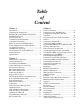
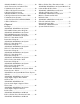
Table of Content Chapter 1 Chapter 3 Introduction ..........................................................3 Unpacking the Components .................................3 Mounting the Central Matrix Components ..........3 ADAM Circuit Cards ...........................................3 Front Card Access ................................................3 Card Removal and Installation ............................4 Unused Back Card Slots ......................................
ADAM, ADAM CS or Zeus ............................. 30 Audio Connections for Other 4-Wire Communications Systems ................................. 30 4-Wire Call Signal Connections ....................... 31 Call Signal Connections for ADAM, ADAM CS, and Zeus .......................... 31 Call Signal Connections for Other 4-Wire Communications Systems ................................. 31 4-wire Call Send and Call Enable/Inhibit ......... 31 4-Wire Call Receive ..........................................
CHAPTER 1 Introduction Unpacking the Components Unpack the contents of the shipping crates and carefully inspect for damage. Notify the freight carrier immediately if any damage is noted. Check off all items as noted in the packing lists. SAFETY TIP: Use caution when lifting the system components. A fully loaded ADAM Card Frame, for example, weighs approximately 75 lbs (34kg). Mounting the Central Matrix Components Bolt the ADAM Card Frame into the front of the equipment rack.
Introduction Card Removal and Installation All ADAM circuit cards can be “hot-installed”, which means you do not have to turn the power OFF before installing or removing a card. This permits continuous operation of the intercom system - with no interruptions to unaffected ports - in the event of a card failure. READ THIS BEFORE INSTALLING CIRCUIT CARDS! The connector pins on the back plane inside the ADAM frame can be easily damaged by improper or hurried insertion of the circuit cards.
AC Power Connection To install a power supply, set the power switch on the front of the supply to the OFF position. Push the power supply firmly into the slot in the ADAM frame so that the connector sits properly in the slot, then tighten the captive screws. AC Power Connection 1. Place the AC switches on the back panel of the ADAM frame in the OFF (O) position. 2. Place the power supply ON/OFF switch on the front of each power supply in the OFF (O) position. 3.
Introduction Specifications Matrix Size........................................................................................................................................................ 8 - 1000 ports Matrix Type:.................................................................................................................................... Digital Audio, TDM Bus Signal Format:..........................................................................................................................
CHAPTER 2 Intercom Port Connections General Information Typically, devices are connected to individual intercom ports using Station Breakout Panels as shown in the in the drawings starting on page 33. Depending on the type of breakout panels being used, the individual intercom stations will utilize either RJ-11 modular style intercom cables, or 9-pin D-sub cables. Wiring diagrams for both are shown in the Figure 22, “Intercom Station Cables,” on page 54.
Intercom Port Connections General Procedure for Connecting Devices to the Intercom The following is a suggested method for planning the intercom system and connecting devices to intercom ports: • Make a copy of the Intercom System Planning Worksheet, see Table 10 on page 17. (Or create your own custom tables using your favorite spreadsheet or database program). • For each device that will be connected, fill in a row in the worksheet.
KP-32 Installation Notes Refer to the KP-12 User Manual (p/n 9350-7497-001) for complete user information. KP-32 Installation Notes Use either FRAME connector (but not both) on the back of the keypanel to connect to an intercom port at a Station Breakout Panel. • To connect an expansion panel, use the cable supplied with the expansion panel. Connect from the EXPANSION connector of the KP-32 to either the CONTROL connector on the expansion panel.
Intercom Port Connections Connections INTERCOM- Use either of the “To Matrix” connectors (but not both) to connect to an intercom port. The intercom port that you connect to will determine the address of the unit. An LED labeled “Data’ is located next to the Matrix connectors and serves as a basic indicator. TELEPHONE and TELEPHONE LINE- There are two telephone connections provided on the rear of the TIF system. Plug the telephone line into the jack labeled “To Phone Line”.
CDP-950 Camera Delegate Panel Installation Notes Installing the CDP-950 1. Before installing the CDP-950, remove the top cover and set the internal DIP Switches: DIP #1 DIP #2 Normal/ISO Select Closed: Normal Operation Open: ISO Operation Baud Rate Select Closed: 9600 baud Open: 76,800 baud (Do not use for ADAM) DIP #3 Not Used (position does not matter) DIP #4 - #8 Intercom range select (see Table 4 on page 14 for settings.) 2.
Intercom Port Connections TABLE 1. ADAM Master Controller Card (MC-ADAM 9002-7514-100) DIP Switch Settings (S1)a Description On=Closed, Off=Open Default Setting On=Closed, Off=Open Switch No. AZedit baud rate selectb 1 OFF: 9600 ON ON: 38.4 Key Incoming Message Optionc 2 OFF: Normal Operation OFF ON: All callers displayed in Incoming Messages window Keypanel “busy” and “in-use” flashd 3 OFF: Enable OFF ON: Disable Trunk Master baud rate selecte 4 OFF: 38.
TABLE 2. MCII-e Factory set DIP Switch Settings DIP Switch 1 Debug Only! Must be in OPEN position. Sets the baud rate for AZedit serial connection via J1. By default, AZedit is set for COM1 and 38,400 kbps (38.4k). The baud rate set in AZedit must match the baud rate setting of the Master Controllers in ADAM. DIP Switch 2 Default: OPEN OPEN: 9600 baud CLOSED: 38.4k baud DIP Switch 3, 4, and 5 Reserved, keep in OPEN position. DIP Switch 6 Debug Only! Must be in OPEN position.
Intercom Port Connections TABLE 4. Address DIP Switch Settings for KP-95, 96, 97, 98 Keypanels and the TIF Address DIP Switch Setting Logical Keypanel Number SW4 SW5 SW6 SW7 1 DOWN UP UP UP 2 UP DOWN UP UP 3 DOWN DOWN UP UP 4 UP UP DOWN UP 5 DOWN UP DOWN UP 6 UP DOWN DOWN UP 7 DOWN DOWN DOWN UP 8 UP UP UP DOWN 9 DOWN UP UP DOWN 10 UP DOWN UP DOWN NOTE: The shaded area is for CS9xxx system address only! TABLE 5.
KP-32 Addressing KP-32 Addressing A rotary switch is used to indicate the logical port address the keypanel is to use when communicating with the Matrix. The switch is read continuously through polling by the matrix. If the port address is changed, the new address is effective immediately. NOTE: The address pot, by default is shipped with an invalid address to ensure that there are no conflicts with existing keypanels.
Intercom Port Connections TABLE 8.
KP-32 Addressing a. Dependent on UIO-256 DIP Switch SW1 Settings for Input/Output Range as summarized in Table 7. Inputs will sink 100mA max at a maximum input voltage of +18 VDC For operation from an external DC voltage source, connect the external control voltage to the “+” pin, and connect the external common to the “” pin. The UIO265 also has an internal 18 VDC source, which is available at pins 18 to 22. Ground is available at pins 24 and 25.
Intercom Port Connections TABLE 10. Intercom 18 System Planning Worksheet Intercom Port No. ADAM Audio I/O Card No.
KP-32 Addressing TABLE 10. Intercom System Planning Worksheet Intercom Port No. ADAM Audio I/O Card No.
Intercom Port Connections TABLE 10. Intercom 20 System Planning Worksheet Intercom Port No. ADAM Audio I/O Card No.
CHAPTER 3 Device Connections Connections to the ADAM Frame An ADAM Intercom System can be setup in a variety of configurations to meet different user requirements. Several common variations are illustrated in the system drawings starting on page 33. Configuration Computer Connection and Check Use an RS-232 serial cable to connect from J1 of the XCP-ADAM-MC Breakout Panel to COM1 or COM2 of the configuration PC.
Device Connections TABLE 11. PAP Addresses IFB Range Model Default Ports for Program Input Panel No. (Default = 1) Low (Default) High PAP-940 1-24 1-4 1-40 41-80 PAP-950-50 1-50 1-4 1-50 51-100 PAP-951 1-8 1-4 1-12 13-24 PAP-952 1-16 1-4 1-24 25-48 The intercom port addresses for program input, as well as the low and high ranges for IFB output, are stored in EPROM memory in the PAP.
Connections to the ADAM Frame PAP-32 Program Assign Panel The PAP-32 connects to J3 on the ADAM system, port 902 on an ADAM CS system. The baud rate, as will all UIO-256, PAP, and LCP-102 devices is fixed at 76.8k baud. A cable must be made to connect the PAP-32 to the system. See the following figures for the proper cabling diagram. FIGURE 1. PAP D-sub Cable Diagram FIGURE 2.
Device Connections Viewing the Program Source for an IFB Press an IFB destination key which has an IFB assignment (i.e., is not blank/). The IFB key’s lower LED will be turned on solid red. If the specified IFB has a program source, the lower LED for the key which has that program source assigned will turn on solid red for as long as the IFB key is held on.
UIO-256 Input/Output Frame UIO-256 Input/Output Frame Connecting a single UIO-256 Frame 1. Connect a single UIO-256 to J3 of the Master Controller Breakout Panel, as shown in ADAM-101 through ADAM-108 interconnect diagrams starting on page X. Use a RS-485 data cable wired as shown in the ADAM -809 installation drawing on page 53. If a PAP is also being used, it may be wired to the same connector. Alternatively, use a punch block or other connector system. 2.
Device Connections Connecting to the SSA-324 General Description The SSA-324 is a System-to-System Adapter (or interface). It interconnects the voice signals between different types of intercom systems. In addition, it can optionally interconnect intercom systems. Also, it can optionally interconnect “Calls” or tally signals between systems. Each SSA-324 includes two, 2-wire to 4-wire converters. The 4-wire interface can deliver and accept high-level signals such as those from the McCurdy intercom system.
Connecting to the SSA-324 TB1 Four Wire Connections System A TB1- System B TB1- Audio In Hi 1 5 Audio In Lo 2 6 Audio Out Hi 3 8 Audio Out Lo 4 8 J104 Power Input Earth 1 16VAC 2 16VAC 3 No Conn.
Device Connections Front Panel Dyn. Mic Headset Connector 1 Mic Lo 2 Mic Hi 3 Headphone Com 4 Headphone Hi Motherboard Test Signal Jumper Place jumper on W2 for tone test signal, W3 for voice test signal. Test signal used with headset and front panel nulling adjustments to null return 2-wire signal. Operation Controls and Connections Front Panel Switches 1. Channel Select switch, CH1 out / CH2 in, Sys A. 2. Press momentary switch for nulling System A, 2-wire 3.
Connecting to the SSA-324 Rear Panel Switches Unbalance (Out) Balance (In) / Select Two-wire, System A Unbalance (Out) Balance (In) / Select Two-wire, System B Operation Nulling Preset Controls as follows: To/From RTS Set to Midway Duck Level Set to CW Low Set to Midway Med Set to Midway Hi Set to CW Volume 10 o’clock Press Test Switch 1. If test signal tone, adjust Med for null, then Hi, then Low. If test signal voice, say “ahhhhh” into microphone, adjust Med for null, then Hi, then Low. 2.
Device Connections Connecting to an SSA-424 General Description The SSA-424 Dual Digital Hybrid interfaces two, 2-wire intercom lines to two, 4-wire intercom lines. Unlike earlier analog hybrids, the SSA-424 features advanced digital signal processing to achieve automatic nulling of the 4-wire lines. Plus, each hybrid features convenient peak-reading level meters to quickly match the levels between the lines that are being interfaced. The result is an easy and accurate setup.
Connecting to an SSA-424 4-Wire Call Signal Connections NOTE: These connections will require the call signal option. Part Number 9002705500. Call Signal Connections for ADAM, ADAM CS, and Zeus You can use the General Purpose Interface (GPI) connector to interface the call signals. The pin-out of the connector is the same for all of these intercom systems.
Device Connections 32
CHAPTER 4 Drawings 33
Drawings 34
FIGURE 3.
FIGURE 4.
FIGURE 5.
FIGURE 6.
FIGURE 7.
FIGURE 8.
FIGURE 9.
FIGURE 10.
FIGURE 11.
FIGURE 12. ADAM Intercom System Matrix Frame Layout - AIO-16 +2.1V +2.
FIGURE 13.
FIGURE 14.
FIGURE 15.
FIGURE 16.
FIGURE 17.
FIGURE 18.
FIGURE 19.
FIGURE 20.
FIGURE 21.
FIGURE 22.
FIGURE 23.