
Specifications


60 - Connecting Serial Devices DeviceMaster Installation and Configuration Guide: 2000506 Rev. B
DB9 Null-Modem Cables (RS-232)
Wire the following pins together for an RS-422 loopback plug:
•Pins 2 to 3
•Pins 7 to 8
DB9 Null-Modem
Cables (RS-232)
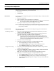
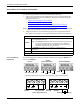
Use the following figure if you need to build an RS-232 null-modem cable. A null-modem
cable is required for connecting DTE devices.
Note: You may want to purchase or build a straight-through cable and purchase a null-
modem adapter. For example, a null-modem cable can be used to connect COM2 of
one PC to COM2 of another PC.
DB9 Null-Modem
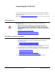
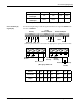
Cables (RS-422)
Use the following figure if you need to build an RS-422 null-modem cable.
Note: RS-422 pinouts are not standardized. Each peripheral manufacturer uses different
pinouts. Please refer to the documentation for the peripheral to determine the
pinouts for the signals above.
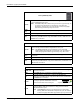
DB9 Straight-Through
Cables (RS-232/485)
Use the following figure if you need to build an RS-232 or RS-485 straight-through cable.
Straight-through cables are used to connect modems and other DCE devices. For example,
a straight-through cable can be used to connect COM2 to a modem.
Pin 1
Pin 5
Pin 6
Pin 9
RS-422 Only
(Back View)
DeviceMaster
TxD
RxD
RTS
CTS
DSR
GND
DCD
DTR
Signal
RxD
TxD
CTS
RTS
DTR
GND
DCD
DSR
Signal
DB9
2
3
8
7
4
5
1
6
Pins
DB25
3
2
4
7
8
6
Pins
20
5
Female
DB9
3
2
7
8
6
5
1
4
Pins
RJ45
5
4
1
3
6
7
Pins
2
8
DeviceMaster
TxD+
TxD-
RxD+
Signal
Female
DB9
7
3
8
Pins
RxD+
RxD-
Signal
TxD+
TxD-
RxD- 2
DeviceMaster
DB9
1
2
3
4
5
8
6
7
Pins
DCD
RxD
TxD or TRxD-
DTR
GND
CTS
DSR
RTS or TRxD+
Signal
DB9
1
2
3
4
5
8
6
7
Pins
DCD
RxD
TxD or TRxD-
DTR
GND
CTS
DSR
RTS or TRxD+
Signal
Female
RI 9
9RI
RJ45
6
5
4
2
3
8
7
1
Pins
N/A
DB25
8
3
2
20
7
5
6
4
Pins
22