
Specifications


58 - Connecting Serial Devices DeviceMaster Installation and Configuration Guide: 2000506 Rev. B
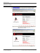
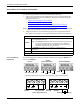
DeviceMaster 2-Port (1E/2E) DB9 Connectors
DeviceMaster 2-Port (1E/2E) DB9 Connectors
Use the following information to connect the DeviceMaster UP 2-port.
1. Connect your serial devices to the appropriate serial port on the DeviceMaster UP
using the appropriate cable.
Use the following table and the appropiate discussion to build cables or loopback
plugs.
• DB9 Loopback Plugs
on Page 59
• DB9 Null-Modem Cables (RS-232) on Page 60
• DB9 Null-Modem Cables (RS-422) on Page 60 (also supports RS-485 full-duplex)
• DB9 Straight-Through Cables (RS-232/485)
on Page 60
Note: Refer to the hardware manufacturer’s installation documentation if you need help
with connector pinouts or cabling for the serial device.
2. Verify that the devices are communicating properly. Use the appropriate table for
information about the LEDs, which may provide information about the installation.
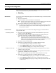
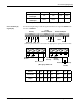
DB9 Connector Pinouts
Pin RS-232
RS-422
RS-485 Full-Duplex
(Master/Slave)
RS-485
Half-Duplex
1 DCD Not used Not used
2RxD RxD- Not used
3 TxD TxD- TRxD-
4 DTR Not used Not used
5GNDNot used† Not used†
6 DSR Not used Not used
7RTS TxD+ TRxD+
8CTS RxD+ Not used
9 RI Not used Not Used
† Pin 5 is tied to ground on the board, but is not used in
the cable.
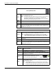
2-Port LED Descriptions
STATUS
The STATUS LED on the device is lit, indicating you have power and it
has completed the boot cycle.
Note: The STATUS LED flashes while booting and it takes
approximately 15 seconds for the Bootloader to complete the cycle.
When the Bootloader completes the cycle, the LED has a solid,
steady light that blinks approximately every 10 seconds.
LINK
If the LINK (green) LED is lit, it indicates a working Ethernet
connection.
ACT If the ACT (yellow) LED flashes, it indicates network activity.
Note: For additional LED information, go to the STATUS LED table on Page 97.