
Specifications


DeviceMaster Installation and Configuration Guide: 2000506 Rev. B Hardware Installation - 31
16/32-Port Rack Mount Models (Internal Power Supply)
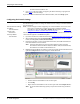
3. Connect the DeviceMaster port labeled 10/100 NETWORK to the same Ethernet
network segment as the host PC using a standard network cable.
If you plan on using the NS-Link device driver, make sure that you do not connect
RS-422/485 devices until the appropriate port interface type has been configured
in the driver. The NS-Link default port setting is RS-232.
4. Apply power to the DeviceMaster by connecting the appropriate power cord into the
power socket on the DeviceMaster, plugging the power cord into a power source, and
turning on the power switch.
5. Verify that the Status LED has completed the boot cycle and network connection for
the DeviceMaster is functioning properly using the table below.
6. Go to Initial Configuration
on Page 33 for default network settings and how to
configure the DeviceMaster for use.
Larger picture, Page 94
Larger picture, Page 94
DeviceMaster RTS
Larger picture, Page 94
DeviceMaster Serial Hub
Caution
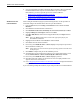
16/32-Port (Internal Power Supply) LED Descriptions
Status
The amber Status LED on the device is lit, indicating you have power and it
has completed the boot cycle.
Note: The Status LED flashes while booting and it takes approximately 15
seconds for the Bootloader to complete the cycle. When the
Bootloader completes the cycle, the LED has a solid, steady light that
blinks approximately every 10 seconds.
LNK/
ACT
The red LNK/ACT LED is lit, indicating that you have a
working Ethernet connection.
Duplex
If the red Duplex LED is lit, it indicates full-duplex
activity.
100
If the red 100 LED is lit, it indicates a working 100 MB
Ethernet connection (100 MB network, only). If the LED
is not lit, it indicates a 10 MB Ethernet connection.
Note: For additional LED information, go to the Status LED table on Page 97.
LNK/
ACT
Duplex
100
10/100 ETHERNET