
Specifications


18 - Hardware Installation DeviceMaster Installation and Configuration Guide: 2000506 Rev. B
Attaching the Network and Serial Cables
After mounting the DeviceMaster, you are ready to connect the cables.
Attaching the Network
and Serial Cables
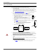
Use the following procedure to attach the serial ribbon and Ethernet cables. For a larger
illustration of the system, see 1-Port Embedded
on Page 92.
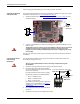
1. Attach the ribbon cable built in Building the Serial Ribbon Cable
on Page 16 to the
header labeled J3.
2. Connect a standard Ethernet cable from the RJ45 port on the DeviceMaster to your
Ethernet hub.
The default serial port setting on the DeviceMaster is RS-232. Do not connect the
serial device until you have configured the serial port settings. You must
configure network settings and upload firmware before configuring the serial
port settings.
Use the next subsection to wire the power terminal connector and verify the hardware
installation.
Connecting the Power
and Verifying
Installation
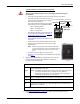
Use the following procedure to wire the power terminal connector and connect the
DeviceMaster to a power source.
Observe proper ESD techniques when connecting and disconnecting the
DeviceMaster.
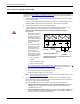
1. Insert the earth ground wire into the earth ground screw terminal.
2. Insert the DC positive wire into the positive
screw terminal and the DC return wire into the
return screw terminal.
If you purchased the Comtrol power supply
(separately), the wires are identified below:
• Red = 5-30VDC positive
• White = 5-30VDC return
• Black = earth ground
If you did not purchase a power supply from
Comtrol for the DeviceMaster, see 1-Port
5-
30VDC Power Supply on Page 87 for power
requirements.
3. Use a small flat head screw to lock the wires
into place.
4. Verify that each wire has been tightened securely.
Ethernet
10/100
Connector
J3
12
910
Caution
Caution
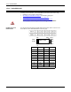
Earth Gnd
Return
Positive
5-30VDC
+
-
Wire gauge:
AWG 12-22
Screw Terminal Power Connector