TM GETTING STARTED TM 1 8 16 24 PO W ER STA TU S RE S ET ™ 9330-7634-000 Rev C , 8/02
PROPRIETARY NOTICE CUSTOMER SUPPORT The RTS product information and design disclosed herein were originated by and are the property of Telex Communications, Inc. Telex reserves all patent, proprietary design, manufacturing, reproduction, use and sales rights thereto, and to any article disclosed therein, except to the extent rights are expressly granted to others. Technical questions should be directed to: PATENT NOTICE This equipment contains and uses a design embodied in United States Patent No.
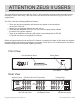
ATTENTION ZEUS II USERS The original Zeus manual ships with the Zeus II. This information sheet provides information that is relevant to Zeus II users only. If the front of the unit does not have the Zeus II logo, the unit is an original Zeus. The Zeus II has the following additional features: ! There are two power supplies and therefore two power cord connections on the rear of the unit. ! Simply plug in the power cords to turn the unit on.
ICP-2000 To Other RTS Matrix Intercom System example: Adam CS (J901) TM ICP-2000 J1 J2 J3 J4 J5 J6 J7 J8 To TM-2000 TELEX COMMUNICATIONS, INC. MADE IN USA See TM-2000 Manual Telebyte Configuration See TM-2000 Manual See Diagram 2 Set to DTE To Zeus II (J28) DIP Swtich Settings Pos. 1 2 3 4 5 Telebyte RS-232 to RS-485 Converter Model 285M or Model 365M Setting Closed (on) Open (off) Open (off) Closed (on) Open (off) NOTE: Unit is set for RS-485 twowire mode via DIP switch.
End-User License Agreement for Telex® Software IMPORTANT - Please read this document carefully before using this product. THIS DOCUMENT STATES THE TERMS AND CONDITIONS UPON WHICH TELEX COMMUNICATIONS, INC. (the COMPANY) OFFERS TO LICENSE THE INSTALLED SOFTWARE OR PROGRAM (the SOFTWARE) FOR USE WITH THE PRODUCT IN WHICH IT WAS INSTALLED. YOU ARE AGREEING TO BECOME BOUND BY THE TERMS OF THIS AGREEMENT. IF YOU DO NOT AGREE TO THE TERMS OF THIS AGREEMENT, DO NOT USE THIS PRODUCT.
This page intentionally left blank.
Table of Contents Read Me First! · · · · · · · · · · · · · · · · · · · · · · · · · · · · · · · · · · · · · · · · · · · · · · · · · · · · · · · · · · · · · · · · · 7 Introduction · · · · · · · · · · · · · · · · · · · · · · · · · · · · · · · · · · · · · · · · · · · · · · · · · · · · · · · · · · · · · · · · · · · 7 Zeus General Description · · · · · · · · · · · · · · · · · · · · · · · · · · · · · · · · · · · · · · · · · · · · · · · · · · · · · · · · · · · · 9 Specifications · · · · · · · · · · · · · · · · · ·
List of Figures Figure 1. Reference view for Zeus DSP Intercom Matrix · · · · · · · · · · · · · · · · · · · · · · · · · · · · · · · · · · · · · · · · · · · 8 Figure 2. Zeus and Accessory Dimensions · · · · · · · · · · · · · · · · · · · · · · · · · · · · · · · · · · · · · · · · · · · · · · · · · · 11 Figure 3. A possible intercom system layout for the sample configuration file named 1studio.zus. · · · · · · · · · · · · · · · · · · · · · 12 Figure 4.
1 Read Me First! If you don’t read anything else in this manual, at least read these important notes: • Make sure that the Zeus frame has adequate ventilation. Allow at least 1 rack unit (1.75 inches, or 45 mm) of open space above and below Zeus at all times during operation. Also, do not obstruct the vents at both sides. • The help file for ZEUSedit is intended to be your primary document when learning how to use the software.
8 Getting Started, Zeus™ DSP Intercom Matrix Status Indicators: 2 rows of 24 LED's each Top Row: Green "keypanel connected" indicators. One for each intercom port. On only when a keypanel or TIF-951 is connected and operating on the port. Bottom Row: Red "frame activiity" indicators. LED 1 On = System Ok. LED 2 On = Audio Ok. LED 3 On = ZEUSedit on-line. LED 4 = UIO-256 connected LED 5 = LCP-102 connected.
3 Zeus General Description Zeus is a versatile, 24-channel intercom signal router and controller which you configure from an IBM compatible PC. You use it to create sophisticated, small- to mid-size intercom systems. Using ZEUSedit configuration software for Windows®, you configure the channels to meet the unique communication needs of each user of the system. In the simplest application, for example, you can create a two-way communication channel between a user on channel 1 and a user on channel 2.
4 Specifications 4.1 Zeus Description A 24-channel, software configurable, audio signal router and controller for complex, small- to mid-size intercommunication systems. Power Input IEEC power connector with fuse and power switch. Internal switching power supply accepts 90-250 VAC, 50/60 Hz, 60 Watts max.
6 17 .9 5 in m m 43 in .3 m 17 9 m 44217.4 mm in in 17 2 mm 43 KP96/KP97 Keypanel 2R Us 3 99 .9 i m n m 2R Us Zeus DSP Intercom Matrix in m 17 m 2 43 7 in mm 178 42916.9 mm in EKP96/EKP97 Expansion Keypanel for KP96/KP97 7 17 .0 8 in m m 2R Us in .3 m 17 9 m 43 LCP-102 Level Control Panel 6 17 .8 3 in m m 2R Us in .0 m 17 2 m 43 LCP-100A Level Control Panel 8. 21 5 6 in m m 1R U in .0 m 17 2 m 43 UIO-256 Universal Input/Output Frame 1R U 1R U 4 12 .
Po Pa we ge red (P Sp St AG e ud E) ake io r STUDIO Talent 1 (TAL1) Talent 2 (TAL2) Talent 3 (TAL3) 4020M 4020M 4020M 22 22 22 Floor Manager 2 (FM-2) 13 Camera 1 (CAM1) 4-Wire Internal 12 Floor Manager 1 (FM-1) BP-318 Camera 3 (CAM3) 4-Wire Internal Camera 2 (CAM2) 4-Wire Internal 18 12 12 Lighting Director (LTG) BP-318 18 BP-318 18 19 19 20 20 20 19 Spare 20 19 TW5W #1 AUDIO Audio Operator (AUD) (PGM1) (PGM2)(PGM3) KP96-7 Mixing Console 16-Key Panel 11 PS-15 PC TW5W #2
5 About the Sample Configuration Files, 1studio.zus and 2studio.zus 5.1 Introduction Included on the ZEUSedit installation disk are two sample intercom system configuration files. We’ve also prepared sample system diagrams to go along with the sample files. We’ll provide a detailed explanation for the first sample file. The second sample file does not include anything that can’t be found in the first example. Rather, it is included just to give you an idea of an alternate configuration.
☞ We’re going to make a suggestion now, which we 3. Now click on the Port Alpha button. 4. You should now be looking at the list of names for intercom ports. A printout of this list is shown in Table 3. This printout was obtained using the File, Print command in ZEUSedit. You’ll notice that most of the “Alpha” names in the list are the same as names in parenthesis in the studio illustration.
TAL1 is not an intercom port, it’s an Interrupt Foldback (IFB). By the way, if you aren’t familiar with this term, you could always get a description of it from the help file. Click on the Search button, then follow the instructions to search for IFB. 6. Let’s assume that you are familiar with the term, and just move on to entering a name. Click the Other Alpha button. 7. As you can see, there are several other types of intercom resources, in addition to intercom ports, that can be named. Table 4.
Table 5. A partial printout of the IFB configuration list for the sample intercom setup file 1studio.zus IFB Alpha Dim? Scroll Enable Input Port Input Alpha Output Port Output Alpha 001 TAL1 -9.0 dB YES 021 PGM1 021 PGM1 002 TAL2 -9.0 dB YES 022 PGM2 022 PGM2 003 TAL3 -9.
Figure 4. The keypanel setup screen for the director’s keypanel in the example file 1studio.zus ☞ Note: To get on-line help with keypanel setup, as well as some of the terms used below, press the F1 key while viewing any keypanel’s setup screen in ZEUSedit. Notice that all listen keys are assigned as “AF”. This is the auto-follow special function. This means that each listen key will automatically follow, or have the same assignment as, the talk key directly beneath it.
16. Using the 1studio.zus example, we’ve now taken you through virtually all the steps that are typically required to set up an intercom system. First, you name the intercom ports and any other types of communication (IFB’s, ISO’s etc.) that you will need. Then you configure any special types of communication that you have named. Then you assign the things you’ve named and configured to intercom keys on keypanels.
Figure 6. Accessing the Analog Input / Output Gain Adjustment. You use this adjustment when you want to change the level for a particular channel, and the change will affect all channels when talking or listening to that channel. (To adjust the level between two particular channels only, use Crosspoint Gain.) Figure 7. The analog input / output gain adjustment table. Note that all channels are set to the default level of 0 dB. However, in the 1studio.
20. An intercom configuration file such as the 1studio.zus example can be created either off-line or on-line. Whichever method is used, the configuration changes must be downloaded to Zeus in order to take effect. Downloading changes while working on-line If the computer is communicating with Zeus while you are making changes, ONLINE will be indicated in the lower-right corner of the ZEUSedit screen.
STUDIO 1 AUDIO 1 Audio Operator (AUD1) (PGM1) (PGM2) KP95-0 Mixing Console Talent 1 (IFB1) Talent 2 (IFB2) 4020M 4020M 22 22 14 14 11 Camera 1 (S1C1) 4-Wire Internal VIDEO 1 Video Video Tape Operator (VID1) Operator 1 (VTR1) KP95-0 12 Floor Manager (S1FM) KP95-0 Camera 3 (S1C3) 4-Wire Internal Camera 2 (S1C2) 4-Wire Internal 12 12 Lighting Director (LTG1) BP-318 11 11 18 BP-318 18 CONTROL ROOM 1 Technical Director (DIR1) Director (TD-1) KP95-0 KP95-0 PC 11 11 19 20 15 TW5W #1
6 Cables and Connectors 6.1 Introduction XLR CONNECTORS 9-Pin Male 3-Pin Male G Each Zeus intercom system will have unique requirements for cables, so it is not practical to supply these with Zeus. A computer interconnect cable has been provided, but even this may not be long enough for your system layout requirements. Most cables will need to be custom built. Following is some useful general information for those who are not familiar with cable construction.
6.4 Cable Diagrams DE-9P (MALE) TO KEYPANEL OR TIF-951 +1 -2 + - DATA 6 9 7 8 3 AUDIO TO ZEUS 1 1 2 6 2 6 + - Note: Shields optional. If used, do not connect at keypanel end! FROM AN EXTERNAL AUDIO SOURCE + - 4 5 9 + - +4 -5 DE-9S (FEMALE) TO ZEUS J1-J24 DE-9S (FEMALE) TO ZEUS J1-J24 AUDIO TO ZEUS + - Note: Shields optional. If used, do not connect at external device end! 7 + - Figure 11. Keypanel and TIF-951 Intercom cable wiring diagram.
DE-9P (MALE) DE-9S (FEMALE) TO ZEUS J1-J24 DE-9P (MALE) 1+ 2 TO ZEUS J26 TO UIO-256 J2 1 TO SSA-324 TB1 CONNECTOR SYSTEM A OR (B) 3 (7) 4 (8) Figure 17. UIO-256 interconnect cable. 3-PIN XLR (Male) 3-PIN XLR (Female) 2 2 1 1 3 G 3 G To SSA-324 “Y” Cable Shields optional. Connect to Ground (G) Terminal. 2 (6) 1 (5) + Note: Shields optional. If used, do not connect at SSA-324 end! AUDIO TO ZEUS AUDIO FROM ZEUS + - 2 - RS485 DATA 2 6 + - 4 + - +6 -1 7 5 9 8 3 Figure 21.
7 Installation Notes 7.1 General Installation Procedure These are the steps that you should generally use to get your Zeus intercom system up and running. 1. Unpack and inspect the equipment. 2. Organize a set of equipment manuals. (You may have several copies of some types, keypanel manuals, for example.) 3. Mount the Zeus frame and connect it to the configuration computer. 4. Install ZEUSedit on the configuration computer. 5. Log on to Zeus from ZEUSedit. 7.
7.6 ☞ The ZEUSedit status indicator (third from left) will Power-Up and Indications 1. Turn on the Zeus power switch on the back panel. 2. Boot the computer and start Windows. 3. Zeus will take a few moments to power up, during which, the STATUS indicator will be red. After a few moments, the STATUS and POWER indicators should be green to indicate normal operation. 1 RESET POWER be lit whenever Zeus is communicating with ZEUSedit. be lit to indicate normal operation.
7.10 • Keypanel Installation Notes 2. A second modular jack labeled "INST" is also provided for each phone line. This may be used to connect a telephone or other instrument along with the TIF-951. 3. For each connected phone line, connect from the DE-9S connector (labeled "INTCM FRAME") on the back of the TIF-951 to a Zeus intercom channel. Use a 9-pin intercom cable (Figure 11, page 23). 4.
Audio sources can be utilized in several ways within the intercom system: • An audio source can be assigned to a keypanel listen key. This permits the keypanel operator to listen to the source by activating the listen key. To assign an audio source to a key, click the KP button on the toolbar, then press the F1 key for help with keypanel setup. • The audio input to which an audio source is connected can be forced to the output of an intercom port (forced crosspoint).
mally use to assign any port, party line etc. to a keypanel key. There is also another unique way that you can use GPI outputs: you can set them to activate whenever anyone talks to a particular intercom port. This is convenient because it saves you from having to make individual key assignments. The following example compares the two methods of using a GPI output. Example: Suppose you want to be able to talk over a public address system from a keypanel.
7.13.4 Programming GPI Inputs ☞ When an LCP-102 is connected and communicating Using a GPI input is a 2-step process. First you define a particular “key” at a particular intercom port that will be activated by the GPI input. You do this using the GPI IN button on the ZEUSedit toolbar. It is important to note that there does not actually have to be a keypanel connected at the port you select. In fact, there usually is no keypanel connected.
MODEL PS15 POWER SUPPLY O/N 9000678600 PS15 NORM 200 Ω TW5W RTS SYSTEMS, BURBANK, CALIFORNIA MADE IN U.S.A. J1, J2 CONNECT TO TW INTERCOM SYSTEM COMPONENTS REFER TO OPERATION MANUAL FUSE 0.5A SB / 120VAC TIP-CH1 0.25A SB / 240VAC RING-CH2 SLEEVE-COM OUTPUTS IMPEDANCE SELECT DUAL 400 Ω AUDIO COUPLING CH1-CH2 CAUTION FOR CONTINUED PROTECTION AGAINST FIRE, REPLACE ONLY WITH SAME TYPE FUSE.
Addendum Using Low-current Devices with the Zeus GPI Outputs Document: Zeus Getting Started Manual, Rev A Addendum Number: 1 General Instructions: Use this addendum with Revision A of the manual. This information will be included in Revision B. Subject: This addendum includes additional information about the use of the GPI outputs. It can be used together with the GPI connector pin-out information in the Specifications section, page 10, and the GPI connector information starting on page 28.
Addendum 2 Zeus DIP Switches Document: Zeus Getting Started Manual, Rev A Addendum Number: 2 General Instructions: Use this addendum with Revision A of the manual. This information will be included in Revision B. WARNING The following instructions are for use by qualified personnel only. To avoid electric shock, do not remove the cover unless you are qualified to do so. AVERTISSEMENT Les instructions qui suivent s'adressent uniquement a un technicien qualifie.
keypanels that do not have alphanumeric talk key displays, such as the KP95-0 Keypanel. In this case, it may be preferable to have all caller's names appear in the Incoming Messages window, since it will not be possible to identify which talk key to press for talk back. 3. The in-use flash is indicated by a slow and continuous flashing display above a talk key (for keypanels equipped with displays). The in-use flash is provided for IFB's and ISO's. It is also provided for trunk lines (ADAM systems only).
Errata Zeus GPI Output External Transistor Connection Document: Zeus Getting Started Manual, Rev A Errata Number: 1 The following instructions correct errors in Revision A of the manual. This information will be included in Revision B of the manual. General Instructions: Figure 24, page 28: Replace Figure 24 in the manual with the one shown below.