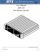
User Manual LMS-325 Line Monitor Speaker ;;;;;;;;; ;;;;;;;;; ;;;;;;;;; ;;;;;;;;; ;;;;;;;;; ;;;;;;;;; ;;;;;;;;; RT S LM S3 25 VO LU M E 9350-7490-000 Rev D 11/2006
PROPRIETARY NOTICE SHIPPING TO THE MANUFACTURER The product information and design disclosed herein were originated by and are the property of Telex Communications, Inc. Telex reserves all patent, proprietary design, manufacturing, reproduction, use and sales rights thereto, and to any article disclosed therein, except to the extent rights are expressly granted to others. All shipments of product should be made via UPS Ground, prepaid (you may request from Factory Service a different shipment method).
CHAPTER 1 Description and Specifications .................................................................................... 1 General Description .................................................................................................... 2 Features ....................................................................................................................... 2 Controls .......................................................................................................................
CHAPTER 1 Description and Specifications What you will find in this chapter: •General Description •Features •Controls •General Specifications •Connector Pin Configurations •Speaker Amplifier Specifications 1
Description and Specifications General Description The LMS-325 is a modular amplified speaker that can be used to maonitor one or two intercom or program channels. The LMS-325 is a five-watt. eight-ohm modular amplified speaker for use with RTS rack or console-mounted intercom systems. Features Features of the LMS-325 include: • • • • • Two monaural phone jacks for two separate audio inputs. One 3-pin XLR connector for RTS intercom channels one and two. Control to adjust volume of speaker output.
Connector Pin Configurations Environmental Requirements Storage: -20°C to 80°C; 0% to 95% humidity, non-condensing. Operating: 0°C to 50°C; 0% to 95% humidity, non-condensing. Dimensions 1.72” (44mm)H x 8.2”(208mm)W x 8” (203”)D Weight 2 lbs. 12 oz. (1.25kg) Connector Pin Configurations Speaker Inputs Type: Type: Pin 2 Pin 3 External Power Type: RCA Phone Jacks Tip: Audio Sleeve: Common XLR-3F Pin 1 Common RTS Channel 1 audio RTS Channel 2 audio 2.
Description and Specifications 4
CHAPTER 2 Operation What you will find in this chapter: •External Connections & Controls •Mounting Configurations 5
Operation External Connections & Controls NOTE: The numbers refer to the callouts in Figure 1. 1. Volume Control Use this control to simultaneously adjust the speaker level for both speaker input lines. 2. 3. 12-15 VDC Input Jack The LMS-325 is powered from a Telex® Wall Pack (part number 532006-000). Plug the Wall Pack inot the 12-15 VDC jack and into an AC outlet. Balance Control This control adjusts the relative level of the Input 1and Input 2 (Channel 1 and Channel 2, respectively).
Mounting Configurations Mounting Configurations Optional mounting configurations for modular RTS™ intercom stations are shown in Figure 2 and include rack-mount, console-mount, desktop, and portable stations. ; ; ;;; ; Figure 2.
Operation 8
CHAPTER 3 Replacement Parts What you will find in this chapter: • • • Where to obtain parts Mechanical Parts Electrical Parts 9
Replacement Parts Where to Obtain Parts Parts may be obtained directly from Telex at: Telex/RTS Systems 12000 Portland Ave South Burnsville, MN 55337 800-392-3497 Fax 800-323-0498 Mechanical Parts TABLE 3. Mechanical Parts Final Assembly (Refer to page 19 for Item No. locations Item No. Description Part No. 1 Speaker Grill Assembly, LMS-325 9020-7490-000 2 Foam Strip, 1/4” Wide, Grey, 6.0” LG. 4501-0076-02 3 *6* Case Extrusion 9060-6260-00 4 P.C.
Mechanical Parts TABLE 4. Speaker Grill Assembly Speaker Grill Assembly (Refer to Pages 20-21 Item No. locations) Item No. Description 8 Part No. Washer, Lock 50049-003 9 Speaker 590530-000 10 Screw 51845-056 11 Conn.
Replacement Parts TABLE 5. Electrical Parts PC Board Assembly Refer to Page 23 for Reference No. Qty Ref. No. Description Part No. R28 R29 R30 8 R31 Resistor, CF, 10 kΩ, 5%, 1/4 W 52154-257 R7 Resistor, CF, 1.8 kΩ, 5%, 1/4 W 52154-275 R27 Resistor, CF, 2.7 Ω, 5%, 1/4 W 52154-343 Resistor, CF, 0 Ω, 5%, 1/4 W 52154-971 Capacitor, Cer. Disc. 10 pF 500 V. 10% 52157-502 Capacitor, CM, 0.33 μF, 50V 52676-512 Capacitor, CM, 1 μF, 50V 52676-517 Capacitor, CM, 0.
Mechanical Parts TABLE 5. Electrical Parts PC Board Assembly Refer to Page 23 for Reference No. Qty 2 Ref. No. C22 C23 Description Part No. Capacitor, EL, 0.1 μF, 25V 517004-000 1 R13 Potentiometer, 10kΩ, 30%, 0.08W 14060044-00 1 R18 Potentiometer, 10kΩ, 20%, 0.1W 14090060-00 U2 IC, Low Noise Dual Op-Amp, LM833N 1603083300 Terminal with Insert.
Replacement Parts 14
CHAPTER 4 Drawings In this chapter: • • • • 9010-7490-000 LMS-325 Final Assembly Drawing 9020-7490-000 Speaker Grill Assembly 9027-7490-000 LMS-325 Schematic Drawing 9030-7490-000 Speaker Unit Assembly Drawing 15
Drawings 16
17
18
19
20
21