
Intercom System User Manual


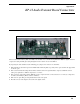

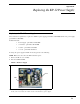
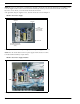


Table Of Contents
- READ ME FIRST
- CHAPTER 1 Menu List for DKP-8, DKP-12, and KP-12 Keypanels
- CHAPTER 2 Power-Up and Initial Settings
- CHAPTER 3 Basic Intercom Operation
- CHAPTER 4 Telephone Operation
- CHAPTER 5 Using the Top-Level Menu
- General Description
- Top Level Menu, - - - - (Clear call waiting)
- Top Menu Level, Call List Names
- Top Level Menu, Display
- General Description
- Top Level Menu, Display, CHANS ON
- Top Level Menu, Display, Exclusive
- Top Level Menu, Display, Group (1-4)
- Top Level Menu, Display, KEY ICOM
- Top Level Menu, Display, KEY TYPE
- Top Level Menu, Display, Level 2
- Top Level Menu, Display, Listen
- Top Level Menu, Display, Page Use
- Top Level Menu, Display, Port Num
- Top Level Menu, Display, SOLO
- Top Level Menu, Display, Version
- Top Level Menu, Key List
- Top Level Menu, Level
- Top Level Menu, Lists
- Top Level Menu, Menus
- Top Level Menu, Page (1-4)
- Top Level Menu, TGL LISN (Toggle Listen ON/OFF)
- CHAPTER 6 Menu Mode
- Select Control Operation in Menu Mode
- Menus, Autodial (for KP-12/DKP-12 Only)
- Menus, KEY ASGN
- Menus, KEY ASGN, General Description
- Menus, KEY ASGN, AUTODIAL (For KP-12, DKP-12 Only)
- Menus, KEY ASGN, AUTOFUNC
- Menus, KEY ASGN, CLEAR
- Menus, KEY ASGN, COPY
- Menus, KEY ASGN, LISTS
- Menus, KEY ASGN, LISTS
- Menus, KEY ASGN, LISTS, IFB
- Menus, KEY ASGN, LISTS, IFSL
- Menus, KEY ASGN, LOCAL I/O (For KP-12 Only)
- Menus, KEY ASGN, PHONE (For KP-12, DKP-12 Only)
- Menus, KEY ASGN, REDIAL (For KP-12, DKP-12 Only)
- Menus, KEY ASGN, UPL
- Menus, Key Opt Menu
- General Description
- Menus, KEY OPT, BTN LOCK (Button Lock)
- Menus, KEY OPT, CHIME
- Menus, KEY OPT, CLR OPT
- Menus, KEY OPT, COPY
- Remember to save you changes if you want them retained for future use. See “Menus, SERVICE, SAVE ...
- Menus, KEY OPT, EXCLUSIVE
- Menus, KEY OPT, GROUP (1-4)
- Menus, KEY OPT, LATCHING
- Menus, KEY OPT, SOLO
- Menus, SERVICE MENU
- General Description
- Menus, SERVICE, DIMMER
- Menus, SERVICE, FOOT SW (with GPI module ONLY)
- Menus, SERVICE, KEY TYPE
- Menus, SERVICE, LOCK/UNLOCK
- Menus, SERVICE, MIC CTRL
- Menus, SERVICE, MIC COMP
- Menus, SERVICE, MIC GAIN
- Menus, SERVICE, MOD ASGN
- Menus, SERVICE, MUTE LVL
- Menus, SERVICE, OPTO-ISO (KP-12 with GPI Module Only)
- Menus, SERVICE, OUT CTRL
- Menus, SERVICE, RESET
- Menus, SERVICE, SAVE CFG
- Menus, SERVICE, SET ADDR
- Menus, SERVICE, SIDETONE
- Menus, SERVICE, TALLY
- Menus, SERVICE, TEST PNL
- Menus, SERVICE, TONE
- Menus, SERVICE, USM (Unswitched Microphone, for KP-12 with Rear Connector Module Only)
- Appendix A KP-12 Audio Transmit Board Connections
- Appendix B Replacing the KP-12 Power Supply

52
NOTE: If you have an older chassis, you will need to attach the 3 metal tabs as shown in the figure below. You will also need
to use the supplied washer on the screw hole with no metal tab (the washer goes between the board and the chassis hole).
If you have a new chassis, you can discard the metal tabs and washer.
4. If applicable, using the supplied screws, attach the metal tabs as shown in Figure 2.
5. Using the screws from the old power supply, attach the power supply to the chassis.
NOTE: Place the washer between the new power supply and the chassis screw hole.
6. Reattach CN1 and CN2 (see figure below).
7. Replace the cover on the KP-12.
FIGURE 2. New Power Supply
FIGURE 3. New Power Supply- Installed
Metal Tab
Metal Tab
Metal Tab
Washer
Be sure to place between
the chassis and the power
supply.
NOTE:
Make sure to place
the metal tabs
exactly as shown.
CN2
CN1