
Intercom System User Manual


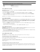
Table Of Contents
- READ ME FIRST
- CHAPTER 1 Menu List for DKP-8, DKP-12, and KP-12 Keypanels
- CHAPTER 2 Power-Up and Initial Settings
- CHAPTER 3 Basic Intercom Operation
- CHAPTER 4 Telephone Operation
- CHAPTER 5 Using the Top-Level Menu
- General Description
- Top Level Menu, - - - - (Clear call waiting)
- Top Menu Level, Call List Names
- Top Level Menu, Display
- General Description
- Top Level Menu, Display, CHANS ON
- Top Level Menu, Display, Exclusive
- Top Level Menu, Display, Group (1-4)
- Top Level Menu, Display, KEY ICOM
- Top Level Menu, Display, KEY TYPE
- Top Level Menu, Display, Level 2
- Top Level Menu, Display, Listen
- Top Level Menu, Display, Page Use
- Top Level Menu, Display, Port Num
- Top Level Menu, Display, SOLO
- Top Level Menu, Display, Version
- Top Level Menu, Key List
- Top Level Menu, Level
- Top Level Menu, Lists
- Top Level Menu, Menus
- Top Level Menu, Page (1-4)
- Top Level Menu, TGL LISN (Toggle Listen ON/OFF)
- CHAPTER 6 Menu Mode
- Select Control Operation in Menu Mode
- Menus, Autodial (for KP-12/DKP-12 Only)
- Menus, KEY ASGN
- Menus, KEY ASGN, General Description
- Menus, KEY ASGN, AUTODIAL (For KP-12, DKP-12 Only)
- Menus, KEY ASGN, AUTOFUNC
- Menus, KEY ASGN, CLEAR
- Menus, KEY ASGN, COPY
- Menus, KEY ASGN, LISTS
- Menus, KEY ASGN, LISTS
- Menus, KEY ASGN, LISTS, IFB
- Menus, KEY ASGN, LISTS, IFSL
- Menus, KEY ASGN, LOCAL I/O (For KP-12 Only)
- Menus, KEY ASGN, PHONE (For KP-12, DKP-12 Only)
- Menus, KEY ASGN, REDIAL (For KP-12, DKP-12 Only)
- Menus, KEY ASGN, UPL
- Menus, Key Opt Menu
- General Description
- Menus, KEY OPT, BTN LOCK (Button Lock)
- Menus, KEY OPT, CHIME
- Menus, KEY OPT, CLR OPT
- Menus, KEY OPT, COPY
- Remember to save you changes if you want them retained for future use. See “Menus, SERVICE, SAVE ...
- Menus, KEY OPT, EXCLUSIVE
- Menus, KEY OPT, GROUP (1-4)
- Menus, KEY OPT, LATCHING
- Menus, KEY OPT, SOLO
- Menus, SERVICE MENU
- General Description
- Menus, SERVICE, DIMMER
- Menus, SERVICE, FOOT SW (with GPI module ONLY)
- Menus, SERVICE, KEY TYPE
- Menus, SERVICE, LOCK/UNLOCK
- Menus, SERVICE, MIC CTRL
- Menus, SERVICE, MIC COMP
- Menus, SERVICE, MIC GAIN
- Menus, SERVICE, MOD ASGN
- Menus, SERVICE, MUTE LVL
- Menus, SERVICE, OPTO-ISO (KP-12 with GPI Module Only)
- Menus, SERVICE, OUT CTRL
- Menus, SERVICE, RESET
- Menus, SERVICE, SAVE CFG
- Menus, SERVICE, SET ADDR
- Menus, SERVICE, SIDETONE
- Menus, SERVICE, TALLY
- Menus, SERVICE, TEST PNL
- Menus, SERVICE, TONE
- Menus, SERVICE, USM (Unswitched Microphone, for KP-12 with Rear Connector Module Only)
- Appendix A KP-12 Audio Transmit Board Connections
- Appendix B Replacing the KP-12 Power Supply

Menu Mode
42
Using Multiple Expansion Panels (KP-12 Only)
When using multiple expansion panels, some MOD numbers may have to be reassigned so that each group of 4 keys has its
own unique MOD number. Table X shows the correspondence between MOD numbers, key numbers, and setup pages.
Example 1, connecting one EKP-20 along with a KP-12. Use the default MOD numbers as shown in Table 4 on page 40.
Next, assign setup pages. See “Top Level Menu, Page (1-4)” on page 22.. You should assign one setup page as MAIN. This
page will correspond to the keys on the KP-12. Assign a second setup page as “EXP1”. This page will correspond to the first
16 keys on the EKP-20. Assign a third setup page as “EXP2”. The first 4 keys on this setup page will correspond to the
remaining 4 keys on the EKP-20. The remaining 12 keys on the setup page are not used. If you want to connect LCPs, you can
use one LCP-12 and one LCP-20 without changing the ROMs.
Example 2, connecting two EKP-20 Expansion Panels along with a KP-12. From Table 4 on page 40 you can see that the
EKP-20 has default MOD numbers 5 through 9. One of the EKPs must therefore be reprogrammed to use MOD 10 through
14. Also, assign one setup page a “Main”. (To assign setup pages, See “Top Level Menu, Page (1-4)” on page 22..) This page
will correspond to the keys on the KP-12. Assign a second setup page as “EXP1”. This page will correspond to the first 16
keys on the first EKP-20. Assign a third setup page “EXP2”. The first 4 keys on this setup page will correspond to the first 12
keys on the second EKP-20. The remaining 12 keys on this setup page will correspond to the first 12 keys on the second EKP-
20 Assign the last setup page as “EXP3”. The first 8 keys on this page will correspond to the remaining 8 keys on the second
EKP-20. The remaining 8 keys on the setup page are not used. If you want to connect to LCPs, you can use one LCP-12 for the
KP-12 and one LCP-20 for the first EKO-20 without changing the ROMs. You will have to change the ROM in the second
LCP-20, however, to match the MOD number for the second EKP-20.
Menus, SERVICE, MUTE LVL
The front panel speaker is muted by 12dB whenever a talk key is activated. This is done to prevent possible feedback between
the microphone and speaker. Headphones are muted 6dB, also to prevent possible feedback, especially with open-air sty head-
phones. The muting levels for speaker and headphones are independently adjustable as follows:
TABLE 5. The relationship between setup pages, key numbers and MOD numbers.
Setup Page 1
Keys 1-4 MOD 1
Keys 5-8 MOD 2
Keys 9-12 MOD 3
Keys 13-16 MOD 4 (Do not assign this MOD ever! It is used exclusively for the SELECT control and call waiting display.)
Setup Page 2
Keys 17-20 MOD 5
Keys 21-24 MOD 6
Keys 25-28 MOD 7
Keys 29-32 MOD 8
Setup Page 3
Keys 33-36 MOD 9
Keys 37-40 MOD 10
Keys 41-44 MOD 11
Keys 45-48 MOD 12
Setup Page 4
Keys 49-52 MOD 13
Keys 53-56 MOD 14
Keys 57-60 MOD 15
Keys 61-64 MOD 16