
User`s guide


12
Names of things and what they do
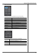
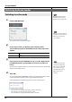
Fader layer buttons
fig.ScrLayer.eps
These buttons switch the layer operated by fader modules 1–24. The currently
selected layer is shown in blue.
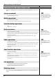
Fader modules 1–24
fig.ScrFader1-24.eps
Use these faders to operate the input channels, AUX channels, MATRIX channels, and
DCA channels.
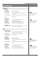
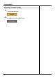
Main fader module
fig.ScrFaderMain.eps
This fader controls the MAIN L/R.
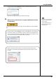
SENDS ON FADER button Accesses the SENDS ON FADER panel.
CH1-24 button Assigns CH1–CH24 to fader modules 1–24.
CH25-48 button Assigns CH25–CH48 to fader modules 1–24.
AUX/MTX button or
AUX/DCA button
Assigns AUX1–AUX16 and MATRIX1–MATRIX8,
or AUX1–AUX16 and DCA1–DCA8 to fader modules 1–24.
SEL button Selects the corresponding channel. The button of the selected chan-
nel is shown in green.
SOLO button Turns a channel’s Solo on/off. The button is shown in orange if Solo is
on.
MUTE button Turns a channel’s Mute on/off. The button is shown in red if Mute is on.
Fader Adjusts the signal level of the channel.
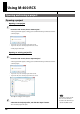
SEL button Selects the MAIN L/R channel. The button is shown in green when se-
lected.
SOLO button Turns the MAIN L/R channel’s Solo on/off. The button is shown in or-
ange if Solo is on.
Fader Adjusts the signal level of the MAIN L/R channel.
Adjustments made to a
selected channel strip in M-
400 RCS will be reflected in
the appropriate M-400
channel strip, but the M-400
display will not switch its
display to your selected
channel strip in the M-400
RCS.
T
oggling the SEL button, you
will alternate between
selecting the MAIN L channel
and the MAIN R channel.