INSTALLATION MANUAL XTO-IP ALARM PANEL DOC. - REF. 230-XTO-IP MODIF. DATE : JANUARY 2016 FIRMWARE VERSION : XLP.05.21.00.
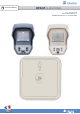
INSTALLATION MANUAL INTRODUCTION Description The XTO-iP is a fully wireless alarm system. It can be powered by standalone batteries or connected to a power supply. This panel has been designed for outdoor installations, with its weatherproof casing and extended operating temperature range. With the Motion Viewers™ and Videofied® range of products, the XTO-iP panel provides video verification in case of intrusion. The XTO-iP panel has three wired programmable inputs and two wired programmable outputs.
INSTALLATION MANUAL SUMMARY Introduction............................................................................................................2 Summary..................................................................................................................3 1. XTO-iP panel setup..........................................................................................................4 1.1 SIM card installation...................................................................................
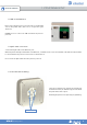
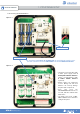
1. XTO-IP PANEL SETUP INSTALLATION MANUAL 1.1 SIM card installation Before removing the front cover from its box, Put the SIM card on the plastic base (Take care to respect the right direction). DO NOT insert or remove the SIM card while the panel is powered. 1.2 RJ45 cable connection Connect the RJ45 cable to the Ethernet port. When the panel attempts a transmission via Ethernet, a red LED on the connector will flash.
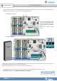
1. XTO-IP PANEL SETUP INSTALLATION MANUAL 1.4 Powering and initialization Option 1 Mains power supply Programming button THE CONTROL PANEL MUST BE CONNECTED TO AN EXTERNAL POWER SUPPLY (OPTION 1) WHEN USING THE RINGTONE FEATURE OR SMARTPHONE APP. Option 2 • The panel is powered either with a mains power supply with 4 backup LR20 Alkaline batteries Option 1 recommended) or with 4 LSH20 Lithium batteries (Option 2). • Always replace all 4 batteries at once.
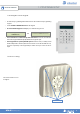
1. XTO-IP PANEL SETUP INSTALLATION MANUAL 1.4 Pairing the remote keypad • Press the XTO programming button and release for the enrollment of a programming keypad. • Insert all LS14500 Lithium batteries into the keypad. • Do not mount the keypad. It will display one of the following screens: RSI (c) 2013 videofied.com or <=========XX=========> • Press on both CLR and ESC NO keys at the same time and release. The indicator LED on the keypad will blink rapidly. Wait for the keypad to pair.
INSTALLATION MANUAL 2. XTENDER MODE The XTO-iP panel can be used as standard standalone alarm system but it can also be connected to an existing alarm system capable of latching a 9-12Vcc* voltage used for its arming/disarming. 2.1 Standalone mode In this functioning mode, the XTO panel works as a standard hybrid alarm system with 25 wireless peripherals and 3 programmable inputs. It is a fully standalone alarm system. 2.
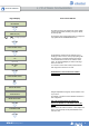
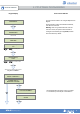
INSTALLATION MANUAL Keypad Display 3. XTO-IP PANEL PROGRAMMING Actions and comments KEYPAD 1 RECORDED OK or YES < - LANGUAGE : - > ENGLISH (UK) for language selection The system can also be programmed in : french, italian, german, dutch, spanish, swedish, portuguese, danish, czech and polish. The language can be changed at any time once the panel is programmed in the MAINTENANCE menu.
3. XTO-IP PANEL PROGRAMMING INSTALLATION MANUAL Keypad display Actions and comments CODE NAME : You may name the installer code using the Alphanumeric Keypad. If using automatic setting (called installer default list), enter the name of the list. OK or YES Warning : If the wrong installers list name is used it cannot be set later, the system must be defaulted. ACCESS 1 REGISTERED Leaving the name blank by pressing ESC NO, it will be named ‘ACCESS 1’ by default.
3. XTO-IP PANEL PROGRAMMING INSTALLATION MANUAL Keypad display Actions and comments PERIODIC TEST Test Periodicity: 1 hour, 12 hours, 24 hours, 48 hours, 7 days or no tests. PERIODIC TEST : 24 HOURS We suggest a 24 hours periodic test call. To select periodicity OK or YES TEST (hour) : 04: OK or YES TEST (minutes) : 04:15 OK or YES CODE/STATE MODIFICATION? OK or YES CODE/STATE MODIFICATION ESC NO ALARM: event transmitted upon occurrence.
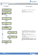
INSTALLATION MANUAL IP1 ADDRESS 0.0.0.0 ESC NO SERVER ADDRESSES ? ESC NO STRATEGY: ETH+2G3G 3. XTO-IP PANEL PROGRAMMING DOMAIN NAME 1 PORT 1 888 The IP1 address, Domain name 1 and/or Port 1 are provided by the monitoring station. Leave Port details at 888 unless otherwise instructed. Press OK or YES to enter/modify the parameter then OK or YES for validation.
3. XTO-IP PANEL PROGRAMMING INSTALLATION MANUAL ETHERNET parameters configuration IP PARAMETERS ? OK or YES DHCP : ENABLED DHCP : DISABLED OK or YES If the router forces a static IP address for the panel, there will then be a need to define DHCP as DISABLED. You will then need to fill in the following network parameters fields : Panel IP, IP Mask, Primary DNS, Gateway and Secondary DNS.
3. XTO-IP PANEL PROGRAMMING INSTALLATION MANUAL For full compatibility with EN50131, press OK or YES. COMPATIBILITY EN 50131 NORMS ? Otherwise, press ESC NO. ESC NO OK or YES Press ESC NO to default the area names. AREAS CONFIGURATION Enter the name of the area 1 and OK or YES. Repeat the procedure for areas 2,3 and 4. For further details, please refer to chapter 4.4.
INSTALLATION MANUAL 3. XTO-IP PANEL PROGRAMMING XTENDER mode configuration ARMING PROFILE : FROM THE HOST OK or YES MODE SLOW : : The panel will arm each device one at a time saving battery life. We recommend this mode. ARMING MODE MODE : SLOW MODE : FAST MODE FAST : The panel will arm all devices at the same time. This mode increases significantly the battery consumption. OK or YES to choose the parameter.
3. XTO-IP PANEL PROGRAMMING INSTALLATION MANUAL Each device has a unique programming button or a specific manipulation. Please refer to the Installation Sheet for the device you would like to program. RECORDING DEVICES PRESS PROGRAM BUTTON OF DEVICE Please check the radio level of each device on its final location. The result must be 8 out of 9 as a minimum (Please refer to the Radio Range section, page 8 for further details).
4. XTO-IP FEATURES GUIDE INSTALLATION MANUAL 4.1 Get to Access level 4 Tue 29/10 DISARMED 11:23 LVL:1 ACCESS LEVEL 1 ACCESS LEVEL LEVEL : 1 OK or YES To unlock and get access to the installer level 4, you need to successively enter TWO codes (in any order) : • INSTALLER CODE (entered during intial programming). • USER CODE (Level3): the user must authorize the installer to get access to the configuration of his panel. ACCESS LEVEL LEVEL : 4 OK or YES BADGE OR CODE OK or YES 4.
INSTALLATION MANUAL 4. XTO-IP FEATURES GUIDE 4.3 How to enable the External RF Antenna CONFIGURATION OK or YES The XTO control panels have built in High Gain RF and GPRS antennas. The GPRS external comes pre-activated and hooked up, while the RF antenna is hooked up but needs to be activated in Configuration after you have completed initial programming. The following steps will walk you through how to enable the High Gain RF antenna after initial programming.
4. XTO-IP FEATURES GUIDE INSTALLATION MANUAL 4.4 Arming and Siren Mode Configuration • Use the to go to menu : CONFIGURATION (LEVEL 4) > SPECIAL ARMING MODES > FULL ARM, SP1 or SP2 use direction arrows to select the arming mode you want to modify and OK / YES. • There are 3 different arming modes : FULL ARM : Arming of all areas and all devices. Use a badge or a user code and press OK / key on the CMA keypad.
4. XTO-IP FEATURES GUIDE INSTALLATION MANUAL 4.5 Manage badges and access codes Access Level Access Level Definition & Rights LVL 1 Standby Level LVL 2 Restricted USER level, where it is only possible to arm/disarm the system. USER level, where it is possible to arm/disarm the system, check the event log, test the devices. LVL 3 Modifications of the settings are not possible at this level. User Level 3 can create Level 2 or Level 3 access codes or badges.
4. XTO-IP FEATURES GUIDE INSTALLATION MANUAL Enter a new end user Badge/Code Delete an end user Badge/Code ENTER A BADGE/CODE BADGES ACCESS CODES Press twice on the right arrow OK or YES ENTER A BADGE/CODE DELETING BADGES/CODES OK or YES OK or YES BADGE OR CODE Badges/codes list Enter a 4-6 digit user code and Select badge/code then OK or YES OK or YES or present a badge in front of the reader until you hear the registration beep.
4. XTO-IP FEATURES GUIDE INSTALLATION MANUAL 4.
4. XTO-IP FEATURES GUIDE INSTALLATION MANUAL 4.7 Read the event log When user disarms the system, the keypad indicates the last event. In case of the user needs to read the full log file, use the keypad to go in EVENT LOG, press OK or YES on SELECT LAST EVENTS and use arrow to list the events. EVENT LOG OK or YES SELECT LAST EVENTS OK or YES 15/10/13 11:29 MODIFIED PARAMET 15/10/13 11:10 SYSTEM DISARMED Press OK or YES for more information about an event 4.
INSTALLATION MANUAL 4. XTO-IP FEATURES GUIDE 4.9 Golden rules 1 Area 1 is always delayed.When you register a keypad or a badge reader into an area, that area will automatically be delayed. 2 Never position a panel next to a high voltage electrical cabinet . 3 Press CLR to erase a typing mistake. 4 Never register the same device twice (delete from the system first). 5 Registration of up to 25 devices (including the keypad). 6 Respect indoor infrared devices installation height (2m10 to 2m30).
5. ETHERNET PARAMETERS INSTALLATION MANUAL To configure Ethernet parameters, using the direction arrows, go to the menu : Lvl. 4 CONFIGURATION OK or YES GENERAL PARAMETERS OK or YES ETHERNET To configure or modify Ethernet Parameters, go to: • IP Parameters: If you wish to use the Ethernet transmission mode, two options are available: DHCP Enable: IP address is assigned by the DHCP service on the network. (Dynamic IP address). This is the default option. 2.
6. TRANSMITTED EVENTS LIST INSTALLATION MANUAL The XTO-iP panel can be configured to enable or disable the transmission of events like alarms or defaults. The installer can modify the default sending settings for those events, although it will end the EN50131 standard compliance. These are the default transmitted events : DEVICE (intrusions) ALERT (Panic Buttons) PANEL LOW BATT. TAMPER DEVICE LOW BATT. PERIODIC TEST DURESS CODE FIRE MEDICAL ASSIST.
7. 2G3G ERROR CODES INSTALLATION MANUAL IMPORTANT: The PIN of the SIM card has to be deactivated or 00000. The following is a list of error codes that can appear after the 2G3G test. In case of 2G3G (GPRS) errors during initial programming, we strongly suggest to continue with the installation and perform the 2G3G (GPRS) level test again once achieved. 2G3G LEVEL : ERROR XXX This error checklist is provided for information purposes only.
INSTALLATION MANUAL 8. TECHNICAL SPECIFICATIONS AND SECURITY NOTES FCC Regulatory Information for USA and CANADA FCC Part 15.21 Changes or modifications made to this equipment not expressly approved by RSI Video Technologies may void the FCC authorization to operate this equipment. FCC Part 15.105 Class B This equipment has been tested and found to comply with the limits for a Class B digital device, pursuant to Part 15 of the FCC Rules.
8. TECHNICAL SPECIFICATIONS AND SECURITY NOTES INSTALLATION MANUAL STANDARDS & CERTIFICATIONS 868MHz ( XTO-iP 210) Compliant with the annex IV from the R&TTE 1999/5/CE Directive 915MHz ( XTO-iP 630) USA FCC (Part 15C , 22H, 24E and 27) Canada IC (RSS-210 Issue 8, RSS-132, RSS-133 and RSS-139) 920MHz ( XTO-iP 730) Australia C-Tick (AS/NZS4268, , AS/CHS42 and AS/NZS 60950) This symbol on the product or on its packaging indicates that this product should not be treated as household waste.
8. TECHNICAL SPECIFICATIONS AND SECURITY NOTES INSTALLATION MANUAL ELECTRICAL DATA TRANSMISSION Communicator Power requirements (option 1) 9-12VDC / 1,2A Power supply Type B 5.15 V Low voltage limit Backup 6V with 4 x 1,5 V D Alkaline batteries /LR20 Low battery limit 4.2 V Battery life (average) 1 year 450µA (over 1h) Average current consumption 1.