
User's Manual
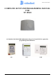
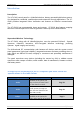
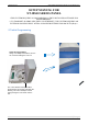
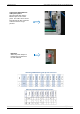
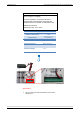
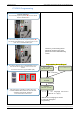
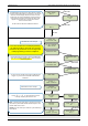
Table Of Contents
- Table of Contents
- Introduction:
- In order for an installation to be UL compliant you must follow the specifications in the table below:
- XT Initial Programming
- XT-IP620 Programming
- Device Installation
- Entering a Badge or Access Code for Arming/Disarming
- Configuration of Special Arming Modes:
- How to Disable/Enable Monitoring
- ETHERNET Parameters:
- How to test to the dispatch center
- How to Disable Monitoring
- How to test RF for deployment of devices
- XT-IP620 Power Chart
- Arming Input Wiring Diagram
- How to test to the dispatch center
- How to mount the XT-IP620
- Troubleshooting
- Monitoring Station is not getting ANY video but is getting signals:
- Monitoring Station is not getting any signals:
- Panel is staying CONNECTED WITH MONITOR STATION
- Unable to record device or getting ‘Pairing Failure’ error
- Outdoor MotionViewer Trips All the Time:
- XT-IP620 -SERIES ‘AFTER INITIAL PROGRAMMING’ FLOW CHART
- 1. LSH20 Control Panel Batteries:
- 2. LS14500 Peripheral Batteries: Excludes SE601 and SE651
- 3. Lithium Battery Storage:
- 4. Finding Manufacture Week and Year:
- 5. Event Log Ethernet Codes
- 6. Additional System Codes
- 7. Replacing Device and Control Panel batteries
- 8. Checking control panel firmware version

2012/1/9 Ed 1.1 Setup and Programming manual for XT-IP620 series
8 | Page
Power Option (PP4)
4 x E95VP Alkaline D-Cell + 12v 2amp DC Class 2
power supply (not supplied)
Used for Standalone or Xtender mode where
Programmable Inputs/Mapping, Programmable
Outputs, Ethernet connection, or SMS will be used
E95VP Specifications:
Operating Temp: 0°F to 130°F
Power Supply Requirements
Output Voltage (volts)
12
Output Current (mA)
2000
Certifications
Class 2 (For UL
Compliance)
E95VP Technical Specifications
Nominal Capacity
8900 mA hours
Nominal Voltage
1.5 V
WARNING:
1. DO NOT USE ALKALINE BATTERIES IF INSTALLING
BELOW 30° F