
User's Manual
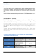
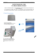
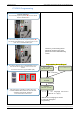
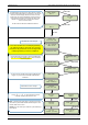
Table Of Contents
- Table of Contents
- Introduction:
- In order for an installation to be UL compliant you must follow the specifications in the table below:
- XT Initial Programming
- XT-IP620 Programming
- Device Installation
- Entering a Badge or Access Code for Arming/Disarming
- Configuration of Special Arming Modes:
- How to Disable/Enable Monitoring
- ETHERNET Parameters:
- How to test to the dispatch center
- How to Disable Monitoring
- How to test RF for deployment of devices
- XT-IP620 Power Chart
- Arming Input Wiring Diagram
- How to test to the dispatch center
- How to mount the XT-IP620
- Troubleshooting
- Monitoring Station is not getting ANY video but is getting signals:
- Monitoring Station is not getting any signals:
- Panel is staying CONNECTED WITH MONITOR STATION
- Unable to record device or getting ‘Pairing Failure’ error
- Outdoor MotionViewer Trips All the Time:
- XT-IP620 -SERIES ‘AFTER INITIAL PROGRAMMING’ FLOW CHART
- 1. LSH20 Control Panel Batteries:
- 2. LS14500 Peripheral Batteries: Excludes SE601 and SE651
- 3. Lithium Battery Storage:
- 4. Finding Manufacture Week and Year:
- 5. Event Log Ethernet Codes
- 6. Additional System Codes
- 7. Replacing Device and Control Panel batteries
- 8. Checking control panel firmware version

2012/1/9 Ed 1.1 Setup and Programming manual for XT-IP620 series
5 | Page
Introduction:
Description:
The XT-IP620 control panel is a Videofied wireless, battery operated hybrid alarm system.
It is designed for residential, small business and commercial security applications. The XT-
IP620 provides integrated Video Verification and features an Ethernet communication
path.
The XT-IP620 has programmable inputs and outputs. XT-IP620 also features mapping
where an external input can be used to generate a video clip from a MotionViewer.
Supervised Wireless Technology:
The XT-IP620, along with all Videofied devices, uses the patented S2View® - Spread
Spectrum, Videofied, Interactive, AES Encrypted Wireless technology, providing
optimum signal integrity and security.
The bi-directional RF communication path between all devices and the system control
panel guarantees high signal reliability. Integrated antennas eliminate protruding wires or
rods, which are difficult to install, unsightly to consumers and potentially troublesome if
damaged.
The panel supervises every device (excluding the remote key fob) to validate current
open/close state, tamper condition, serial number, date of manufacture, firmware revision,
and battery status.
Type
Specifications
Location In Manual
Audio
When a MotionViewer is
installed on the system you
may not have the siren sound
for less than 60 seconds
Page 30
Audio
If no MotionViewer is installed
on the system you may not
have the siren sound for less
than 240 seconds
Page 30
Delays
When a MotionViewer is
installed on the system the
Entry delay must be 45 seconds
Page 9
In order for an installation to be UL compliant you must follow the
specifications in the table below: