
User's Manual
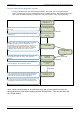
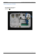
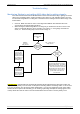
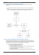
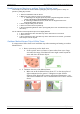
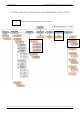
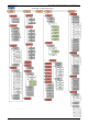
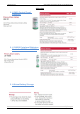
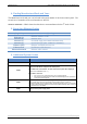
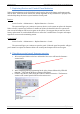
Table Of Contents
- Table of Contents
- Introduction:
- In order for an installation to be UL compliant you must follow the specifications in the table below:
- XT Initial Programming
- XT-IP620 Programming
- Device Installation
- Entering a Badge or Access Code for Arming/Disarming
- Configuration of Special Arming Modes:
- How to Disable/Enable Monitoring
- ETHERNET Parameters:
- How to test to the dispatch center
- How to Disable Monitoring
- How to test RF for deployment of devices
- XT-IP620 Power Chart
- Arming Input Wiring Diagram
- How to test to the dispatch center
- How to mount the XT-IP620
- Troubleshooting
- Monitoring Station is not getting ANY video but is getting signals:
- Monitoring Station is not getting any signals:
- Panel is staying CONNECTED WITH MONITOR STATION
- Unable to record device or getting ‘Pairing Failure’ error
- Outdoor MotionViewer Trips All the Time:
- XT-IP620 -SERIES ‘AFTER INITIAL PROGRAMMING’ FLOW CHART
- 1. LSH20 Control Panel Batteries:
- 2. LS14500 Peripheral Batteries: Excludes SE601 and SE651
- 3. Lithium Battery Storage:
- 4. Finding Manufacture Week and Year:
- 5. Event Log Ethernet Codes
- 6. Additional System Codes
- 7. Replacing Device and Control Panel batteries
- 8. Checking control panel firmware version

2012/1/9 Ed 1.1 Setup and Programming manual for XT-IP620 series
32 | Page
4. Finding Manufacture Week and Year:
The Manufacture week and year can be found in the serial number of the device/control panel. The
second sets of 4 numbers in the serial number are WWYY.
####0411######## = Which shows that this device was manufactured in the 4
th
week of 2011.
5. Event Log Ethernet Codes
Log Code
Meaning
Ethernet Off
Ethernet interface is OFF
Ethernet On
Ethernet interface is ON
Ethernet (0)
Ethernet Error
Ethernet (1)
No DCHP reply (after MAX DHCP RETRY)
Ethernet (2)
No Frontel reply (after TIMEOUT SERVER)
Ethernet (255)
Ethernet communication success
Ethernet Lost
No Ethernet cable detected
Ethernet Returned
Ethernet cable restored
6. Additional System Codes
Codes
Action
999996
Maintenance request
- Ethernet transmission
999995
Displays local IP address assigned to the control panel
:
If the DHCP mode is deactivated : the
static local IP of the panel will be displayed
(defined in the ETHERNET menu
– 7)
If the DHCP is
activated:
• If the panel is not in transmission then 0.0.0.0 will be displayed
•
If the panel is in transmission (the RJ45 led will be flashing) then the dynamic IP
of the panel will be displayed.
999991
Sends a test alarm to IP1 Address (Primary alarm
receiver)
This is a quick way to check for connectivity to the monitoring center. If there is a
transmission problem the panel will terminate communication faster than in an actual alarm.
The system will automatically attempt connection to IP2 Address
(Backup alarm receiver) in
the event that IP1 is unavailable.
999997
Displays external power supply status