
User's Manual
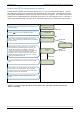
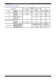
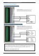
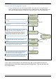
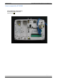
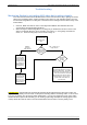
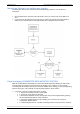
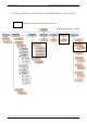
Table Of Contents
- Table of Contents
- Introduction:
- In order for an installation to be UL compliant you must follow the specifications in the table below:
- XT Initial Programming
- XT-IP620 Programming
- Device Installation
- Entering a Badge or Access Code for Arming/Disarming
- Configuration of Special Arming Modes:
- How to Disable/Enable Monitoring
- ETHERNET Parameters:
- How to test to the dispatch center
- How to Disable Monitoring
- How to test RF for deployment of devices
- XT-IP620 Power Chart
- Arming Input Wiring Diagram
- How to test to the dispatch center
- How to mount the XT-IP620
- Troubleshooting
- Monitoring Station is not getting ANY video but is getting signals:
- Monitoring Station is not getting any signals:
- Panel is staying CONNECTED WITH MONITOR STATION
- Unable to record device or getting ‘Pairing Failure’ error
- Outdoor MotionViewer Trips All the Time:
- XT-IP620 -SERIES ‘AFTER INITIAL PROGRAMMING’ FLOW CHART
- 1. LSH20 Control Panel Batteries:
- 2. LS14500 Peripheral Batteries: Excludes SE601 and SE651
- 3. Lithium Battery Storage:
- 4. Finding Manufacture Week and Year:
- 5. Event Log Ethernet Codes
- 6. Additional System Codes
- 7. Replacing Device and Control Panel batteries
- 8. Checking control panel firmware version

2012/1/9 Ed 1.1 Setup and Programming manual for XT-IP620 series
23 | Page
Arming Input Wiring Diagram
When in the ‘Arm From Host’ mode the Videofied system will only arm and disarm when
9-12v is supplied and sustained. When both arming inputs are supplied voltage at the same
time the Videofied Keypad display will show ‘SYSTEM ARMED. When only one arming
input is supplied voltage the Videofied Keypad display will show ‘PART LVL #’
Arming Input 1 will arm/disarm Areas 1 & 2
Arming Input 2 will arm/disarm Areas 3 & 4